Three-phase test track Groß-Lichterfelde – Zehlendorf
The three-phase test route Groß-Lichterfelde – Zehlendorf was a 1.8 kilometer long railway line along Teltower Straße (today Goerzallee) between Lichterfelde and Zehlendorf , which was built by Siemens & Halske exclusively for test drives. The aim of the system was to prove the suitability of electrical operation also in long-distance traffic, i.e. over long distances, and the usability of three-phase current for electrical train operation.
prehistory
After three-phase current found its way into practice at the end of the 1880s / beginning of the 1890s, Siemens & Halske strived to make this type of current usable for electric train operation. To do this, in 1892 she laid out a 360-meter test track on her factory premises in the Wernerwerk in Berlin-Siemensstadt . The power supply with the three phases of the three-phase current was carried out via two overhead lines and the track.
The vehicle for the tests consisted of the undercarriage of a tram on which a platform was mounted. On this platform, the two current collectors, the starting and regulating were resistors and switching devices. The car's engine worked at 1400 revolutions per minute, with which the vehicle reached a top speed of 25 kilometers per hour. In 1893 Siemens & Halske showed the test vehicle at the world exhibition in Chicago .
These first tests worldwide with three-phase current in railway technology clearly showed that drawing and supplying current did not cause any problems and that tests on a larger scale made sense. The authorities did not approve the application made by Siemens & Halske at the time to upgrade an existing route used by steam trains for further tests, as the conversion was found to be too difficult. However, since Siemens & Halske considered the technology to be future-proof, the large investment was made in the construction of a new test track.
investment

The specification for the test track was that speeds of up to 60 kilometers per hour and voltages of up to 10,000 volts would be possible. Various pantograph arrangements should also be tested .
In 1898, Siemens & Halske received permission from the communities of Groß-Lichterfelde and Zehlendorf to use the then undeveloped and little-used Teltower Straße (today Goerzallee between Engadiner Weg and Lichterfelder Weg) for the test route. The facility was completed at the beginning of 1899. The 1.8 kilometer long route was designed in standard gauge and had a slight curve with a radius of 200 meters. A power station with a wagon shed was built roughly in the middle of the route. The overhead line was located on the south side of the street and was equipped with a protective net so that if the overhead line broke during the driving tests, there was no danger to passers-by on the still public road.
tries
Siemens & Halske produced two vehicles for the test drives. It was a locomotive and a transformer car. This transformer car was equipped with two three-pole pantographs, which coated the overhead lines with sliding contacts made of aluminum . The transformer on the car converted the voltage from 10,000 volts to 750 volts. The three overhead lines were parallel in an inclined plane and consisted of eight millimeter thick copper wires. For the first tests and measurements from 1899, the locomotive towed the transformer car. It was shown that the current consumption from above could still be used for speeds of up to 60 kilometers per hour, but with increasing speed the contact bracket at the high points of the overhead line tended to jump off, creating sparks and unsafe contact.
After the overhead lines had been rebuilt, the locomotive was given an iron structure in the spring of 1900, which now also housed a transformer and a three-pole pantograph on the roof for lateral power consumption. The three overhead lines were now in a vertical plane and the pantographs were pressed against the wires by means of spring force.
As part of the test drives, voltages on the contact wire of 750, 2000 and 10,000 volts were used, which were generated directly by the power plant or (at 10,000 volts) produced by transformation. The pantographs behaved better when driving with 10,000 volts than when driving with lower voltage. Overall, the facilities established for the tests after the conversion of the power take-off proved their worth. The locomotive started up at 60 km / h with a load of 30 tons, for example, in 60 seconds with 700 volts and 190 amps of current .
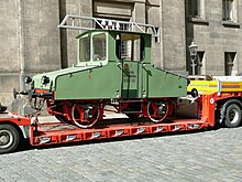
After the end of the test drives, the locomotive used was converted to 220 volts direct current in 1901 and sold to the Bad Berka cement works . In the industrial railway of cement and mineral wool plant Bad Berka she was until 1972 in use. From there it came to the Dresden Transport Museum as an exhibit in 1975 .
Further development

Siemens & Halske brought the experience gained from the driving tests to the study society for electrical rapid transit systems , which was founded together with AEG and which carried out high-speed tests with three-phase current on the military railway between Marienfelde and Zossen from 1901 to 1903 .
Web links
literature
- Walter Reichel: Experiments on using high voltage three-phase current for the operation of electric railways . In: Electrotechnical Journal. Volume 21, issue 23 (June 7, 1900), pp. 453–461.
- Walter Reichel: About the supply of electrical energy for larger rail networks . In: Electrotechnical Journal. Volume 25, Issue 23 (June 9, 1904), pp. 486–493.
- E. Frischmuth: 50 years of electric railways . In: Siemens magazine. 9th year, 5th / 6th Issue (May / June 1929), pp. 263–287.
Coordinates: 52 ° 25 ′ 19 ″ N , 13 ° 17 ′ 54 ″ E


