Casting process simulation
Under casting process simulation is defined as the " modeling ", ie the mapping of casting processes in a simulation - Software . The process of casting and solidification is specified by the software as detailed as possible as a boundary condition for the calculation. The result is a representation of the process of mold filling, solidification, the formation of structure and properties as well as the formation of internal stresses and warpage of the cast parts. “From a single source” means for the modeling the consideration of numerous, mutually influencing technical, physical and chemical influencing variables.
Basics of the casting process simulation
The basis for the casting process simulation is provided by the well-known equations for describing the dynamics of flows, temperature flow, stress development and other mechanical, chemical and thermal processes to be taken into account. The specific casting process is modeled by the boundary conditions under which the software solves the equations.
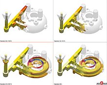
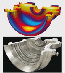
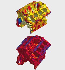
The results of the simulation calculations can be displayed on the screen, printed out as color graphics or in three-dimensional spaces (holographic). They represent a qualitative and quantitative, easily comprehensible documentation of the phenomena of the casting process. They illustrate the process of the mold filling and the solidification. Calculated quality criteria show potential errors and enable the prediction of expected cast part structures and properties. The formation of internal stresses and warpage in the casting can also be predicted. Dynamic processes such as the melt flowing into the mold cavity can be visualized as animations.
These results can be used over the entire life cycle of a casting. At the same time, simulation supports the specification and casting-compliant construction of a cast part, tool construction, the design of stable, economical production through to quality assurance and the optimizing further development of a cast part. The casting process simulation allows a look into the future of the next process step at any time. Before the development of the casting process simulation, this was only possible on the basis of experience and through “trial and error” - which no longer leads to satisfactory results with shorter development times, constantly increasing quality requirements and the need for cost-effective production.
Goals of the casting process simulation
The simulation of casting processes supports the following tasks:
- Examination and improvement of the casting design towards stable, robust casting processes (castable constructions)
- Assessment of the risk of defects in casting (avoidance of casting defects). This is about phenomena of mold filling such as turbulence or eddies, mold erosion, oxide formation as well as phenomena of solidification such as the formation of cavities, structures and internal stresses.
- Assessment and minimization of cast part distortion, which largely depends on the wall thickness distribution in the cast part - i.e. on the design (dimensional accuracy)
- Optimization of casting and heat treatment processes (economic efficiency)
- Design of casting technology with minimal use of raw materials and energy (energy and material efficiency).
- Creation of information, addition of experience (knowledge management).
Stations of a simulation project
Simulation projects basically consist of five steps:
- 3D geometry modeling
- Networking
- Definition of the process parameters
- calculation
- Evaluation of results
The starting point of the simulation is a 3D CAD model of the part to be simulated and the casting system (sprue system, mold, etc.) included in the analysis. In the automotive industry, digital 3D CAD models of the cast parts are usually available. In other industries they often have to be made on the basis of construction drawings.
The meshing divides the geometry to be considered into infinitesimal (volume) segments for the mathematical treatment. When calculating using the finite volume method, the meshing is fully automatic. If the finite element method is used, meshing is also carried out automatically, but manual processing remains necessary. By defining the process parameters (casting performance, shot curve, alloy and casting temperature, tempering medium, mold temperature, etc.), the user completes the necessary requirements to start the calculation. Today the PC platforms have become so powerful that simulation calculations for a project can be carried out several times a day. Multi-core processors enable short computation times even with larger, complex conditions.
In order to evaluate the results, calculation results are output as color-coded graphics or films that dynamically depict, for example, the filling of the casting mold and the solidification of the melt. Depending on which resulting properties are to be considered, for example the formation of internal stresses or porosities, different color tones are assigned to them, which the user can interpret.
The total duration of a simulation project varies with the complexity and the holistic nature of the model to be considered. So z. For example, a thermal analysis of a casting process can be carried out in a period of minutes, usually less than an hour - from the availability of the 3D CAD model of the casting to the evaluated, documented result. The calculation of the mold filling, the solidification and the internal stress generation over several cycles naturally takes longer.
Information from the casting process simulation
Specifically, the simulation shows the following information about the casting process: Mold filling of the cast part
- Course and temperatures of the melt flow
- last filled areas
- Venting the mold
- Accumulation of release agent residues (only with die casting)
- Dead areas in the river
- Swirls in the melt
- Disintegration of the melt
- Meeting of melt fronts
- Cold welds
- Flow figures
Casting solidification:
- Cavities and pores
- Hot cracks
- Structure formation
- Make-up behavior
- Formation of internal stresses and resulting distortion
Information about the tool:
- Support of complete mold filling
- Cycle times
- Core wear
- Tendency to stick
- Loss of heat when spraying
- Life of the mold
Simulation of the process chain
Cast parts often get their ultimate properties from downstream process steps, such as B. from heat treatment or machining. It is therefore essential for the casting process simulation to also deal with these process steps in order to be able to obtain information about the actual properties of a casting in the delivery state.
However, downstream process steps also change the properties of the structure and the casting. Today, with the help of heat treatment simulation, by coupling diffusion calculations and phase changes during cooling, the structure and properties after the heat treatment can be predicted. This helps the steel caster to recognize possible through-hardening problems at an early stage or the aluminum caster to determine the parameters for optimal aging in terms of strength or elongation.
Integration of the simulation in the casting life cycle and foundry processes
The deeper and more comprehensive the simulation is integrated into the life cycle of a casting, the greater its technical and thus also its economic benefit. Since the life cycle is generally cross-company, the casting process simulation should not only be integrated into the processes of the foundries, but also into those of the casting design and at the casting customer.
In the design and construction phase, the casting process simulation helps to develop parts that meet the customer's specifications and at the same time are designed for casting. Potential problems during casting can thus be identified early on and eliminated in the design. This reduces and shortens revision loops and thus accelerates development projects.
After the construction phase, the simulation enables a stable and economical casting process to be set up. The simulation results provide toolmaking with well-founded information for the production of the molds, while production receives reliable parameters in order to set filling curves, ladle control, cycle times, etc. so that they reliably deliver a casting that meets specifications. Before the simulation method was available, foundries had to rely on the individual knowledge of the caster and the trial-and-error results from numerous, expensive test casts during this phase . Now this knowledge is in the software and the theoretically repeated calculation as often as required replaces the real test casting.
Even without using simulation tools, quality assurance benefits insofar as the simulation-supported design and manufacture minimize the production of defective parts and the simulation documents all relevant process steps in the software. The documentation for quality audits by customers or certification bodies is thus created almost automatically. The direct use of the casting process simulation is recommended for continuous quality assurance. It allows z. B. the simple check whether the resilience of a cast part can be increased by changing a process parameter.
Casting process simulation as a communication tool
In addition to the direct influence that the casting process simulation has on the development and production processes of cast parts, it also plays a connecting role in the interdisciplinary and cross-company processes: It serves as a binding "language" that everyone involved can use to communicate . With the objective results of a simulation, for example, design and production can be discussed in depth and decide whether the cast part or casting system needs to be modified or can go straight into production. Without the simulation result, there is no basis for communication. The caster can at most, and cannot be checked by the designer, judge the casting accuracy of a part on the basis of his knowledge and experience. Whether he is right or not can only be determined, if at all, after the first cast parts have been manufactured.
Coupling of casting process simulation and autonomous optimization processes

Until the development of the casting process optimization, casting processes could only be optimized by running through the sequence of steps “trial, testing and modification” several times in order to improve the quality of the cast parts or the profitability of production. In “physical” tests with real models, molds and casting prototypes, the optimizing modifications of production parameters and casting system design are based exclusively on the caster's interpretation of the test results. The casting system remains a “ black box ”, the filling and solidification processes inside are invisible and can only be analyzed by drawing conclusions from the casting result.

The casting process simulation shifts the optimization steps into software that makes the filling and solidification processes visible, analyzable and measurable (and at the same time eliminating the costs associated with the physical tests). The optimizing modifications are no longer based solely on the experience of a caster, but on reproducible, reliable data and generally applicable physical-technical principles.
Advances in computer technology and software development make it possible today to go one step further and to couple simulation methods with optimization processes in order to automate the optimization. Instead of physically or virtually test after test, an autonomously optimizing software calculates different scenarios with varying process parameters and mold layouts after the definition of the optimization goals and the variation ranges for the modifications until the ideal parameter-casting system combination for the realization of the optimization goals is found. The parameter variations can e.g. B. concern production parameters such as casting conditions, materials, mold temperature control, shot curves or spray conditions. In order to determine ideal mold layouts, the pouring runner design, gate and riser dimensioning or cooling channel positioning are modified in the simulations. General production restrictions can also be taken into account.
The autonomous optimization can aim at different, also conflicting criteria, for example the improvement of quality properties on the one hand and the reduction of material consumption on the other hand. As a result, the optimization algorithm then delivers the parameter-casting system combination that provides the best compromise between the two goals.
The history of the casting process simulation
The casting simulation established itself as the most important innovation in the foundry industry between 1960 and 2010. It revolutionized the development and production of cast parts and placed them on a completely new basis.
As early as the 1950s, V. Paschkis was using analog computers to predict the movement of the solidification front in one and two dimensions (1D and 2D). In 1962, K. Fursund was the first to use digital computers to solve problems related to casting ( penetration of steel into the sand mold). In 1965, Hentzel and Keverian published their groundbreaking work on the two-dimensional simulation of solidification in steel castings. They used a program developed at General Electric to simulate heat transfer. Ole Vestby programmed a 2D model in 1968 to study temperature distributions during welding. He used the finite difference method for the first time. Around 1970 Viktor de Lange was using Davies , Ole Vestby's 2D program, to simulate feed lengths in plate-shaped castings. In 1975 Preben N. Hansen received his doctorate with a thesis on the simulation of hot cracking behavior in cast steel parts. In this work, a 3D model was programmed for the first time. At the beginning of the 1980s, research on the subject of “casting process simulation” increased substantially in many places. In addition to the activities at the Technical University of Denmark around Preben N. Hansen, there were working groups in America (Berry and Pelke), Japan (Niyama) and Lausanne (Kurz) as well as Grenoble (Durand) and especially in Aachen at the foundry institute there with the Working group of Peter R. Sahm.
Important milestones were the introduction of the term "criterion function" by Hansen and Berry in 1980, the introduction of a criterion for center line cavities in cast steel parts by Niyama in 1982, and the introduction of a criterion function for hot cracking tendency in cast steel parts by E. Flender and PN Hansen in 1984. At the end of the 1980s First software solutions for simulating mold filling presented.
In the 1990s, developments focused on stress simulation in cast parts (Hattel and Hansen, 1990) as well as the first steps to predict structure and properties, especially by Ingvar Svensson and Magnus Wessén in Sweden.
literature
- JC Sturm, E. Flender: 30 years of casting simulation. In: Foundry. 96, No. 5, 2009, pp. 94-109.
- C. Rogers: A Virtual Tool for the Manufacture and Use of Foundry Cores and Molds. MCWASP 2006 (Opio)
- J. Hattel (Ed.): Fundamentals of Numerical Modeling of Casting Processes. Polyteknisk Forlag, Lyngby 2005, ISBN 87-502-0969-8 .
- V. Kokot, P. Bernbeck: Integration and application of optimization algorithms with casting process simulation. In: Modeling of Casting, Welding and Advanced Solidification Processes X. Destin, Florida, 25. – 30. May 2003 (conference contribution).
- PR Sahm, PN Hansen: Towards Integrated Modeling for “Intelligent Castings”. In: Peter R. Sahm (Ed.): Modeling of Casting, Welding and Advanced Solidification Processes. Vol. IX, Shaker, Aachen 2000, ISBN 3-8265-7230-0 , pp. LXXXI-XCIII.
- PR Sahm, PN Hansen: Numerical Simulation and Modeling of Casting and Solidification Processes for Foundry and Cast-House. CIATF 1984.
- S. Findeisen: Investigations into the heat transport during solidification. VDM Verlag Dr. Müller 2010, ISBN 978-3-639-29263-3 .
Web links
- Casting process simulation makes lightweight construction possible (PDF; 1.4 MB)
- Energy and raw material savings through consistent use of the casting process simulation


