
Main rotor


The main rotor is the two-bladed or multi-bladed dynamic system component of a helicopter , which ensures lift through its rotation around the rotor axis and its control and propulsion through cyclical changes in the angle of attack of the rotor blades . The main rotor basically consists of the rotor shaft (1), the swash plate (2), the control rods (4 and 10), the rotor head with the rotor hub (6), the rotor blade holders with the swivel joints (7) and the rotor blades (9).
Note: All the figures in brackets in this article refer to the legend in the graphic opposite
Helicopter main rotor configurations
Depending on the angle of attack of the rotor blades, the drive of the main rotor generates a torque acting against the direction of rotation of the main rotor on the fuselage of a helicopter. Various constructions are used to counteract the rotation of the trunk around the vertical axis .
Tail rotor configuration
A system of a main rotor and a counter-thrust generating device, which is mounted on a tail boom, is the best known and most common configuration for helicopters. In the tail rotor configuration, a tail rotor attached to the tail boom generates a horizontal thrust in order to counteract the rotation of the fuselage around the vertical axis. This thrust is not constant, but must be adjusted by the pilot with every change in torque (different angle of attack of the rotor blades, changed drive power). In the case of clockwise rotating main rotors ( top view ), the tail rotor is always mounted on the right, and in the case of counterclockwise rotating main rotors on the left side of the tail boom.
A special design is the Fenestron , whose encapsulated design in connection with the larger number of rotor blades and a higher speed allows a smaller rotor diameter with the same power.
Another special design is a system in which no tail rotor can be seen from the outside. Instead, a turbine is mounted in the helicopter that sucks in air near the cabin and blows it out through a nozzle on a boom. An example of this configuration is the McDonnell Douglas NOTAR .
Double rotor configurations
A system of two main rotors rotating in opposite directions is called a double-rotor configuration. A distinction is made between four systems.
Tandem configuration
In this tandem configuration, two main rotors running in opposite directions of the same size are arranged one behind the other in the direction of flight, the rear of the two rotors always being arranged higher than the front. This configuration is used in particular with larger transport helicopters such as the Piasecki H-21 or Boeing-Vertol CH-47 .
Transverse rotors
Rotors arranged transversely are also assigned to the tandem configuration, although two main rotors of the same size, running in opposite directions, are arranged next to one another at the ends of lateral arms across the direction of flight. This configuration comes e.g. B. in the Focke-Achgelis Fa 223 , Mil Mi-12 and Kamow Ka-22 for use.
Flettner double rotor
In this configuration, two rotor shafts are inclined slightly outwards in a V-shape close to one another, so that the two rotors rotating in opposite directions mesh with one another. This configuration comes e.g. B. with the Flettner Fl 282 or Kaman K-Max for use.
Coaxial rotor
In this tandem configuration, two main rotors running in opposite directions are arranged one above the other on a rotor shaft. This configuration comes e.g. B. in the Kamow Ka-32 or Kamow Ka-50 for use. This configuration is also used in entry-level helicopter models.
Blade tip drive
Main rotors with blade tip drive are an exception. In this drive method, the recoil from compressed air, partially supported by fuel combustion (hot blade tip drive), is used to set the main rotor in rotation and thus generate lift. The compressed air is guided through the main rotor mast and the rotor blades to the blade tips, where it emerges from nozzles. Since this force does not act on the rotor shaft, no torque compensation is necessary. However, this drive method was not pursued any further because of the high level of noise and fuel consumption. This drive came z. B. on the Sud-Ouest SO 1221 "Djinn", the only successful helicopter with a blade tip drive. Main rotors with blade tip drive are not discussed further here.
Gyroplane
The main rotor of a gyroplane is not rotated passively by an engine, but rather due to the flow acting from below on the rotor, which is inclined slightly backwards ( autorotation ). This rotation of the main rotor causes the rotor blades to generate lift. The propulsion of the gyroplane takes place, as with the fixed wing aircraft , by a propeller usually attached to the stern . The main rotors of gyroscopes are not considered here.

Kawasaki OH-1 "Ninja" with Fenestron
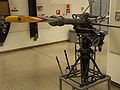
Blade tip drive of the "Djinn"


Components of the main rotor
The main rotor of a person-carrying helicopter and of pitch-controlled model helicopters basically has the following components.
Rotor shaft
The rotor shaft (1) is the central component of the rotor. It is connected to the drive at the lower end via a gear . Internal combustion engines or turbines are used in person-carrying helicopters . In addition to these drives, model helicopters are also operated with electric motors . The drive sets the rotor shaft in a rotary motion. At the upper end of the rotor shaft, the rotor hub is rigidly connected to the rotor head (6). The imaginary line through the center of the rotor shaft is the rotor mast axis. The rotor shaft rotates around this. In most flight situations this is not identical to the axis of rotation of the plane in which the rotor blades are located. The reason for this is the additional inclination that the rotor blades receive during rotation.
The speed of the rotor shaft has a direct effect on the speed of the rotor blade tips of the main rotor. This speed in kilometers per hour (km / h) is calculated using the following formula:


where d stands for the diameter of the rotor circle in meters and the constant 0.06 for the conversion factor in km / h. For example, the Sikorsky S-65 has a rotor blade speed at the blade tip (rotor circle radius = 12 meters, normal rotor speed = 185 revolutions per minute) of 836.92 km / h. In forward flight, the speed of the helicopter must be added to the rotor blade speed. Due to aerodynamic conditions, the helicopter becomes uncontrollable when the speed of the rotor blade tips approaches the speed of sound (approx. 1235 km / h). Without taking atmospheric air currents ( wind ) into account, the theoretical maximum speed of the Sikorsky S-65 is approx. 390 km / h (actually 295 km / h).

The following table shows the speed of the main rotor - given in revolutions per minute (min −1 ) - for a few selected helicopters. In addition, the calculated speed of the rotor blade tips is shown in relation to the rotor circle diameter.
| image | Manufacturer | model | Max. Speed (min −1 ) | normal speed (min −1 ) | min. Speed (min −1 ) | Rotor circle diameter (m) | Max. (km / h) |
|---|---|---|---|---|---|---|---|
 |
|
SA 330 Puma | - | 265 ± 7 | 220 | 15.00 | 769.06 |
 |
|
AS 332 Super Puma | 275 | 265 | 245 | 15.60 | 808.65 |
 |
|
AW189 | 296.14 | - | 284.75 | 14.60 | 814.99 |
 |
|
Bell 47 H-13 Sioux |
380 | - | 300 | 11.35 | 812.98 |
 |
|
Bell 214 | 300 | - | 294 | 15.24 | 861.80 |
 |
|
Bell 222 | 348 | - | 338 | 12.20 | 800.28 |
 |
|
EAC S64F | 193 | - | 185 | 21.95 | 798.53 |
 |
|
EC 225 Super Puma | 275 | 246 | 220 | 16.20 | 839.75 |
 |
|
Hiller UH-12 | 370 | - | 320 | 10.80 | 753.23 |
 |
|
K-Max | 273 | - | 260 | 14.73 | 758.00 |
.jpg) |
|
Bölkow Bo 105 | 433 | - | 403 | 9.84 | 803.13 |
 |
|
MBB / Kawasaki BK 117 | 390.7 | - | 375.3 | 11.00 | 810.10 |
.jpg) |
|
Wed-8 | 186 | - | 179 | 21.91 | 768.17 |
 |
|
R22 | 530 | - | 495 | 7.67 | 766.25 |
 |
|
R44 | 408 | - | 404 | 10.06 | 769.88 |
 |
|
S-58 CH-34 |
258 | - | 170 | 17.07 | 830.15 |
 |
|
S-61 H-3 Sea King |
225 | - | 184 | 18.90 | 801.58 |
 |
|
S-76 | 313 | 293 | 281 | 13.41 | 791.18 |
 |
Various |
Electrically powered model helicopter |
≈ 3000 | ≈ 1700 | ≈ 1000 | 0.90 | 288.40 |
- ↑ m = rotor circle radius (≡ speed of the rotor blade tip)
- ↑ In 1992 Sikorsky sold the rights to the S-64 Skycrane to Erickson Air-Crane
- ↑ with a rotor circle diameter of 0.90 m and 1700 min −1
Swashplate


The swash plate (2) is used to transfer the control movements from the rigid cell to the rotating rotor blades. It is made of two rings (a) (b) which are connected to each other via a bearing (c) so that they can rotate. These rings, which can be moved up and down with the help of a sliding sleeve (d), are mounted around the rotor shaft with a ball joint (e) and are thus gimbaled .
The lower ring (a) of the swash plate (in a different design, the inner) does not rotate with the rotor shaft and is connected mechanically, hydraulically or electronically to the stick attached in front of the pilot's seat and the stick to the side of the control rods (10) (f) Pilot seat attached collective lever (collective pitch) connected.
The upper ring (b) of the swash plate (in a different design, the outer) is connected to the rotor shaft via the driver (3) (g) and rotates at the same speed as it. This ring is connected to the blade adjustment lever (5) mounted on the pivot joint of the blade holder via control rods (4) (h) that rotate with it. In this way, the swivel joints can be controlled and the setting angles of the rotor blades (9) can be changed.
Thanks to the cardanic suspension in connection with the sliding sleeve, the swash plate can perform the following movements:
- Parallel displacement along the rotor shaft for the collective control of the rotor blades. This control movement is entered with the collective lever. The setting angle of all rotor blades is changed simultaneously and by the same amount;
- Inclination of the swash plate in any longitudinal or transverse direction for cyclic control of the rotor blades. This control movement is entered with the control stick. As a result, the rotor blades perform a wave-like change in the setting angle with each revolution of the rotor shaft;
- Combinations of the swashplate movements mentioned above.
Note: All letters in brackets refer to the legend in the adjacent graphic
Control rods


The control elements collective lever and control stick do not belong to the main rotor, but have a direct effect on it. Therefore, it will be discussed briefly here. The collective lever is operated by the pilot with the left hand. So that the latter can operate other instruments, the collective lever does not build up any restoring force, but always remains in the position last set by the pilot. If the helicopter does not have an automatic speed control, z. B. The speed of the drive is controlled via a twist grip. The collective lever is used to initiate the collective control of the rotor blades. The setting angle of all rotor blades is changed by the same amount, so that the lift of all rotor blades is changed equally. The helicopter goes up or down.
The joystick is operated with the right hand. It is used to initiate longitudinal and transverse control inputs that tilt the swash plate in the direction that results from the two tilt angles. This also causes the plane of the rotor blades to incline. The helicopter rotates around its longitudinal (roll) or transverse axis (pitch) .
Since both collective levers and joysticks can act on the control rods at the same time, the control inputs must be able to be mixed. In the case of mechanical mixing gears, the control rods are linked kinematically via reversing levers and the control inputs are mechanically mixed. With hydraulic or electronic support for the control, the control inputs are mixed via the hydraulic or electronic system.
The control inputs of the two control elements are passed on to the swash plate via control rods. For this purpose, the non-rotating ring (a) of the swash plate (2) is connected to the control stick and the collective lever via 3 control rods (f). In order to clearly define the position of the swash plate in space, it must always be controlled with three control inputs. The video shows the interaction of the control rods.
When the collective lever is pulled up, all non-rotating control rods (10) (f) are moved up or down by the same amount, depending on the design of the blade adjustment lever (5), so that the swash plate with the help of the sliding sleeve (d) along the Rotor shaft (1) is moved parallel. As a result, the setting angle of all rotor blades is changed to the same extent, so that the helicopter rises or sinks (regardless of other influences). In most person-carrying helicopters, the rotor blades are set in the lowest position of the collective lever so that they do not generate any lift. The rotor blades of aerobatic model helicopters can be adjusted to generate negative lift so that they can perform an inverted flight.
When the control stick is moved, the control rods are moved up or down by different amounts depending on the design of the blade adjustment lever, depending on the design of the control stick, so that the swash plate controls each rotor blade differently, which is due to the different pitch angles of the rotor blades as they rotate around the rotor shaft (1) Initiates pitching and / or rolling movements.
The co-rotating control rods (4) (h) are connected at one end to the co-rotating ring (b) of the swash plate (2) and at the other end to the blade adjustment lever (5) of the rotor blade (9). They pass on the already mixed control inputs of the collective lever and control stick from the swashplate directly to the rotor blades.
Rotor head with rotor hub
All rotor blades (9) of the main rotor are mechanically attached to the rotor hub of the rotor head (6). The rotor blades can be individually rotated around their longitudinal axis within defined limits via a blade holder with a swivel joint (7), which is also called an angular bearing. This rotation changes the setting angle of the respective rotor blade and thus also the lift generated by it.
The rotor head, like the rotor blade roots , is heavily loaded due to the centrifugal and bending forces as well as the drive torques - in the case of hingeless rotor systems also by torsional forces.
Fully articulated rotor system
A fully moving rotor system is equipped with at least 3 rotor blades. With rigid rotor blades, vertical and horizontal bending forces act directly on the blade root (8) or on the rotor head. They can become so large that the blade root breaks due to these bending forces or the blade holder on the rotor head is severely damaged, which can lead to the helicopter crashing. In order to be able to compensate for these bending forces, each rotor blade in fully movable rotor systems is connected to the rotary joint of the rotor hub via a flapping joint and a swivel joint. So they can be moved around three axes (turn around the longitudinal axis, hit vertically and move horizontally forwards or behind). The freedom of movement of the swivel joint is limited by dampers. The Sikorsky CH-53 is equipped with this rotor system.
Jointless rotor system
The hingeless rotor system is very similar to the fully articulated rotor system. However, no flapping or swivel joints are installed here. The horizontal and vertical bending forces are absorbed by the mechanically flexible rotor blade roots. The Bölkow Bo 105 is equipped with this rotor system.
Rigid rotor system
The rigid rotor system is very similar to the hingeless rotor system. The horizontal and vertical bending forces are absorbed by the mechanically flexible rotor blade roots. However, since no swivel joints are installed here either, the torsion of the individual rotor blades must also be guaranteed by a corresponding flexibility of the rotor blade root. Therefore, rigid rotor systems are made of fiber composites and titanium . The Eurocopter EC 135 is equipped with this rotor system.
Semi-rigid rotor system
A semi-rigid rotor system is equipped with two rigidly connected rotor blades. Like a seesaw, the rotor blades can only swing up and down together. The Bell UH-1 is equipped with this rotor system.
Rotor blade
The rotor blade is the structural element of the main rotor that generates the lift. In the classic design, it is connected to the rotor hub via a rotary, flapping and swivel joint .
materials

For the rotors of helicopters and gyroscopes , steel , titanium , light metal and fiber composites such as B. Glass fiber ( GRP ) and carbon fiber ( CFRP ) composites are used. In the past, wood was also often used. GRP blades were used for the first time on the Kamow Ka-26 and then on the Bo 105 in connection with elastic suspension and a jointless rotor head (cf. swash plate ). The maintenance of the rotor head, which is particularly complex due to the numerous joints in classic designs , is thus significantly simplified, but the blades must be checked regularly for material fatigue.
The rotor blades bear the full weight of the helicopter. In addition, they have to withstand the centrifugal force of the rotation and have the lowest possible weight. To meet these requirements, they are often made of high-strength composite materials. Some rotors are equipped with strain gauges that are used to measure the load during operation.
In the model construction sector, rotor blades made of wood, simple plastic, GRP, CFRP and aluminum are used. In modern CFRP rotor blades for model helicopters , a foam core and a CFRP spar form the framework and give the rotor blade the necessary compressive and flexural strength. The profile is formed from several layers of carbon fiber mats, which provide the necessary torsional strength .
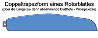
Rotor blade shapes

There are four basic forms of rotor blades for helicopters. In the case of the rectangular shape , which is most frequently used despite poorer aerodynamic properties , the rotor blade has the same depth over the entire length. This design is more cost-effective both to manufacture and to maintain. In the trapezoidal shape , the rotor blade has a decreasing depth from the blade root to the blade tip. Since the flow velocity and therefore the lift at the blade tip is higher than at the blade root, the trapezoidal shape compensates for the dynamic lift over the entire blade length. With the double trapezoidal shape, the depth of the rotor blade first increases from the blade root to the blade center and then decreases again towards the blade tip. In the rectangular trapezoidal shape, the depth from the leaf root to the leaf center is initially the same and then decreases towards the leaf tip :. The ratio of blade length (L) to blade depth (T) is referred to as elongation, abbreviated with and calculated as follows .


- Rotor blade shapes


From 1976 to 1986, the British Experimental Rotor Program (BERP) carried out studies to improve the flight performance of helicopters . As a result of this cooperation between Westland Helicopters and the Royal Aircraft Establishment , a Westland Lynx AH Mk.7 was equipped with BERP rotor blades, which then set a helicopter speed record at 400.87 km / h on August 11, 1986, which will last until May 2010 stayed.
These BERP rotor blades have an aerodynamic twist (see below) and the rotor blade tips have been equipped with paddles that reduce blade tip vortices. The transition from the rotor blade to the paddle, known as a sawtooth, creates a turbulent flow which enables an effective angle of attack that is 6 ° higher before the flow breaks off. On the other hand, BERP rotor blades require a higher drive power.
Rotor blade profiles
In the past, the rotor blade often had a symmetrical profile in order to prevent pressure point migration at different angles of attack and thus the corresponding compensation forces. Such rotor blades have the same profile on the top and bottom and generate neither lift nor downforce at a 0 ° angle of attack. Semi-symmetrical rotor blades have an identical profile on the top and bottom, but this is "thinner" on the bottom. With a positive angle of attack they generate more lift and with a negative angle of attack more downforce than rotor blades with a symmetrical profile. Rotor blades with an S-flap profile are almost straight on the underside and are therefore designed for optimum lift ("lifting force"). They keep the torque forces at the neutral point low.
| profile | Advantages (model helicopter) | Disadvantages (model helicopters) |
|---|---|---|
|
|
|
|
|
|
|
|


The construction of rotor blades with different blade depths is very complex. Nevertheless, to achieve even flow over the entire rotor blade length with the use of rotor blades in a rectangular shape, they are often side set . In the geometric offset z. B. the angle of attack at the blade root is chosen to be large and decreases towards the blade tip (possibly down to 0 °). Geometrically set are z. B. the rotor blades of the Alouette II , Bölkow Bo 105 and the Eurocopter EC 135 .
- Set


aerodynamics
Dynamic lift
Approach velocity


The flow velocity of the rotor blade is not constant over the length of the rotor blade. The speed of a rotor blade section rotating at a distance from the axis of rotation is calculated using the following formula:


where stands for the angular speed of the rotor in radians.

For example, the Sikorsky CH-53 helicopter has a main rotor diameter of 22 to 24 meters, i.e. a radius of 11 to 12 meters, depending on the model variant . In normal operation, the rotor shaft rotates at 185 revolutions per minute (= 19.37 rad / s). This results in a rotor blade speed at the blade tip of 232.48 m / s (≈ 837 km / h). At half the rotor circle ( = 6 m) the rotor blade speed is still 116.24 m / s (≈ 418 km / h). The rotor blade speed at the rotor blade tip is therefore twice as high as at half the rotor circle .

Since the dynamic lift increases or decreases at the same angle of attack of the rotor blades as the square of the inflow speed (in hover flight with no wind roughly identical to the rotor blade speed ), the lift in the hover flight (without considering other factors) at the rotor blade tips is four times greater than at half the rotor circle.
Rotor blade advance

Unless there are other influences, rotor blades, whose focus is on the line running parallel to the rotor blade edge and intersecting the center of the fastening eyelet, stretch precisely into the extension of the rigid blade holder due to the centrifugal forces generated by the rotation .
If the center of gravity of the rotor blade is not on this line, the centrifugal forces do not act on the rotor blade at a 90 ° angle to the axis of rotation, as described above . The front edge of the rotor blade then rotates back and forth around the fastening eyelet until the center of gravity of the rotor blade is again at a 90 ° angle to the axis of rotation, provided that no other influences act on the rotor blade. This behavior is called forward. If the leading edge moves forward, one speaks of positive lead (the blade tip leads in the direction of rotation); if it moves backwards, one speaks of negative lead or lag (the blade tip hangs in the direction of rotation).
The flow resistance to which the rotor blade is exposed due to its high rotational speed reduces the lead or increases the lag of the rotor blade. By constructively shifting the center of gravity, the rotor blade can be adjusted so that it aligns itself as straight as possible in relation to the blade holder in the intended speed range of the main rotor, taking into account the flow resistance, and thus has neither lead nor lag.
In addition to a shifted center of gravity and the flow resistance, aeroelastic effects also have an effect on the advance of a rotor blade.
Efficiency
The efficiency of a rotor can be approximated with the circular area load or the noise development that increases with increasing load can be estimated.
See also
literature
- Walter Bittner: Flight mechanics of helicopters: technology, the flight dynamic system helicopters, flight stability, controllability , Springer Verlag, Berlin and Heidelberg, 3rd edition 2009, ISBN 978-3-540-88971-7
- Ernst Götsch: Luftfahrzeugtechnik , Motorbuchverlag, Stuttgart, 2003, ISBN 3-613-02006-8
- Michael Kalbow: Helicopter Aerodynami , Dieter-Franzen-Verlag, Kuppenheim, 2010, ISBN 978-3-930996-23-0
- Niels Klußmann and Arnim Malik: Lexicon of Aviation , Springer Verlag, Berlin and Heidelberg, 3rd edition 2012, ISBN 978-3-642-22499-7
- Helmut Mauch: The helicopter flight school , GeraMond-Verlag, Munich, 2010, ISBN 978-3-7654-7349-4
Individual evidence
- ↑ a b c d e f g h Niels Klußmann and Arnim Malik: Lexikon der Luftfahrt , Springer Verlag, Berlin and Heidelberg, 3rd edition 2012, ISBN 978-3-642-22499-7
- ↑ a b c d e Michael Kalbow: Helicopter Aerodynamics , Dieter-Franzen-Verlag, Kuppenheim, 2010, ISBN 978-3-930996-23-0
- ↑ a b c d e f Walter Bittner: Flight mechanics of helicopters: technology, the flight dynamics system helicopters, flight stability, controllability , Springer Verlag, Berlin and Heidelberg, 3rd edition 2009, ISBN 978-3-540-88971-7
- ↑ Luftfahrt-Bundesamt, Blaues Buch, excerpt rotary wing aircraft (PDF; 59 kB) accessed on February 11, 2014
- ↑ European Aviation Safety Agency, Rotorcraft Type Certificates ( Memento of the original dated February 22, 2014 in the Internet Archive ) Info: The archive link was inserted automatically and has not yet been checked. Please check the original and archive link according to the instructions and then remove this notice. accessed on February 11, 2014
- ↑ a b c Helmut Mauch: The helicopter flight school , GeraMond-Verlag, Munich, 2010, ISBN 978-3-7654-7349-4
- ↑ ENAE 632 - The British Experimental Rotor Program Blade ( Memento of the original from October 23, 2013 in the Internet Archive ) Info: The archive link was inserted automatically and has not yet been checked. Please check the original and archive link according to the instructions and then remove this notice. University of Maryland, Rotorcraft Aerodynamics Group, Dr. J. Gordon Leishman, accessed October 22, 2013
- ↑ ROTOR magazine, issue 1/2013, p. 47 ff., Modellsportverlag, Baden-Baden
- ↑ ROTOR magazine, issue 1/2013, pp. 48–49, Modellsportverlag, Baden-Baden
- ↑ Niels Klußmann and Arnim Malik, “Lexicon of Aviation”, Springer Verlag, Berlin and Heidelberg, 3rd edition 2012, ISBN 978-3-642-22499-7