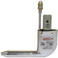
Pitot static system
The Pitot Static System supplies the barometric flight instruments in the cockpit of aircraft with pressure information about the static pressure and the dynamic pressure . Airspeed, altitude and climb or descent can be displayed on the corresponding instruments. An outside temperature sensor must also be installed. The principle mode of operation of the system corresponds to that of Prandtl's Pitot tube .
Measuring principle
As airplanes climb, descend, accelerate, or slow down, the air pressure on them changes. This air pressure in the vicinity of an aircraft is made up of the static pressure (air pressure of the still ambient air, based on the temperature and the existing flight altitude of the aircraft) and the dynamic pressure, which is felt as resistance when moving.
The static air pressure and the dynamic pressure are used in the barometric flight control instruments to determine the flight altitude, the horizontal speed and the vertical speed.
construction
The pitot static system consists of the following parts:
- Pitot tube (named after Henri Pitot , 1695–1771)
- Static ports
- Static pressure line
- Total pressure line
- barometric display instruments in the cockpit ( altimeter , airspeed indicator and variometer )
The pitot tube protrudes into the unaffected air flow and is attached, for example, below a surface with the opening outside of the surface air flow or, in the case of jets, on the tip of the nose. Static ports can be located in different places depending on the aircraft type. There can also be several ports, none of which are directly blown by the air flow.
All three barometric flight control instruments are connected to the static ports via the static pressure line. The airspeed indicator is also connected to the pitot tube via the overall pressure line.
In the case of commercial aircraft (airliners), the variometer is now often fed by the IRS or GPS. These planes also have multiple pitot tubes attached to different locations on the aircraft. The pressure of these pitot tubes is averaged and the separately measured static pressure is subtracted from it. The back pressure thus determined is proportional to the square of the flow rate and can be used for the determination of the IAS ( Indicated Air Speed , German: displayed speed ) can be used.
functionality
The pitot static system in an aircraft is to be understood as a coherent unit. The air pressure in the form of static pressure and dynamic pressure is the medium to be measured. This is measured and displayed on the three barometric instruments altimeter, airspeed indicator and variometer in different units (feet, kts, MpH, m / s). If the pitot static system fails, a controlled flight is hardly possible under instrument flight conditions (IFR), which is why there are multiple devices in aircraft that fly under these conditions. The conventional pitot static measurement systems cannot provide reliable measurements if the airspeed is below 40 knots. A different measurement method is therefore used for helicopters.
Possible errors
In aircraft without a pressurized cabin, there is another alternative static port in the cabin. This port may cause an incorrect instrument reading because the cabin pressure is lower than the outside pressure due to the air flow above the cabin. Speed and altitude then appear higher than real. The variometer shows a temporary increase when the alternate static port is opened, followed by a stabilization phase and a subsequent normal display.
A lock in the pitot static system (icing, insects, dirty splash water, etc.) leads to different errors in the altimeter , variometer and airspeed indicator depending on the location . If misinterpreted, this can even lead to a crash, like the Birgenair accident in the Caribbean in 1996 or the Air France flight 447 over the Atlantic in 2009.
The following is a table of possible pitot static system errors and their effects that every IFR pilot needs to know.
| instrument | Static blockage | Pitot blockage |
|---|---|---|
| Variometer | fixed at 0 | normal display |
| Altimeter | fixed at any value | normal display |
| Airspeed indicator | shows too little speed when climbing
shows too much speed when descending |
shows too much speed when climbing
shows too little speed when descending |
literature
- US Department of Transportation, Federal Aviation Administration - Instrument Flying Handbook , FAA-H-8083-15B, 2012
- Rod Machados's: Instrument Pilot's Survival Manual. 1998.
- US Department of Transportation, Federal Aviation Administration: Airman's Information Manual. Basic Flight Information and ATC Procedures, 1999.
- Jeppesen Sanderson: Private Pilot FAA Practical Test. Study Guide, 2000.
- Jeppesen Sanderson: Private Pilot Manual. 2001.
- Wolfgang Kühr: The private pilot. Technique II, Volume 3, 1981.
- Peter Dogan: Instrument Flight Study Guide. 2000.
- Walter-Air: CVFR textbook. 1994.
- Ozcan Samlioglu, Naval Postgraduate School Monterey CAA: Neural Network Approach for Helicopter Airspeed Prediction. Report number: A155304, MAR 2002.


