Turbo generator
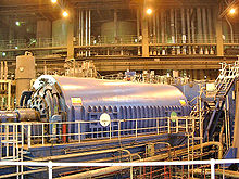
A turbo generator , also known as a full pole machine , is a type of synchronous generator that is primarily driven by high- speed gas or steam turbines. The combination of the turbo generator and the turbine is called a turbo set .
The main area of application of this machine is in the area of medium-sized to larger thermal power plants such as coal or nuclear power plants for the generation of electrical energy . More than 75% of the world's electrical energy is generated using turbo generators.
construction


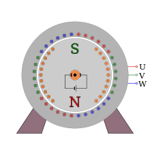
The main differentiating feature from the salient pole machine , which is also a synchronous generator , is the comparatively high speed of 3,000 or 1,500 min −1 in networks with 50 Hz mains frequency and 3,600 or 1,800 min −1 in networks with 60 Hz. To control the centrifugal forces involved the rotor is designed as a slim, long full-pole rotor and operated in a horizontal position. At present, are the maximum feasible diameter of about 1.25 m for 3000 min -1 and 1.15 m for 3600 min -1 . With four-pole machines, the possible rotor diameters are significantly larger (by 2 m for 1500 min −1 ). The limit values result from the currently technically feasible maximum circumferential speeds of up to 235 m / s, with an overspeed factor of 1.2 (20% overspeed based on the nominal speed) being used as a basis for the design.
On the rotor, the grooves are for receiving the excitation winding directly from the massive rotor body (forging) is milled out . The rotor winding is inserted into these slots and wedged. A cap ring is shrunk onto the end of the bale. This prevents the copper windings coming together at the end (rotor winding head) from flying out due to the centrifugal forces. In contrast to the rotor itself, the cap ring consists of high-alloy, non-magnetic steel and, together with the slot wedges, forms an electrically conductive cage on the surface of the rotor, which is called a damper winding . The damper winding is used to reduce shock loads (rotor oscillations) and the heating of the rotor when the load is unbalanced . In the rotor, which is forged from solid steel, no alternating fields and therefore no eddy currents occur under symmetrical loading . An unbalanced load, however, results in a rotating magnetic field in the steel core of the rotor, which can lead to eddy currents and impermissible heating and, in extreme cases, to the destruction of the turbo generator.
To supply the excitation winding with direct current , in older turbo generators, direct current machines , which in this case are also referred to as excitation machines , were used fixedly coupled to the axis . The supply of direct current to the rotor of the turbo generator must then take place via brushes and slip rings.
Today there are mainly two types of excitation common for large turbo generators:
- Brushless excitation with rotating exciter (e.g. external pole machine with diodes for rectification on or in the rotor shaft). The exciter is fed from the outside with a direct current, which is usually made available by a converter system.
- Static excitation: A converter system supplies the direct current, which is transferred to the rotor winding of the internal pole machine via a brush bridge (slip rings and carbon brushes). With this variant, the brushes can easily be exchanged during operation.
Which of the two methods mentioned is used in each case depends, in addition to the respective manufacturer's philosophy, primarily on the requirements of the power plant operator. Both methods have advantages and disadvantages:
- The rotating exciter is normally low-maintenance, but in an emergency, maintenance / repair can only be carried out when the machine is at a standstill. The currents to be processed by the associated rectifier system are comparatively low, but tracking of the excitation current in the event of rapid changes in the operating state is rather slow due to the excitation time constants. To compensate for voltage drops at the generator terminals, the converter system must provide very large voltage reserves (so-called ceiling excitation) compared to normal operation.
- The static converter excitation is overall somewhat more complex in structure, but can largely be maintained online, i.e. H. during the operation of the generator. The currents to be processed correspond to the required excitation currents and are in the range of up to 10 kA for large machines. On the other hand, the static excitation can react very quickly to load changes, whereby the ceiling tension can be significantly lower than with the rotating exciter. This dynamic advantage is becoming more and more important today due to the increasing load flow dynamics in networks with many regenerative energy producers. As a rule, network operators place certain minimum requirements on the generator systems of power plant operators with regard to dynamics and reliability in the event of brief malfunctions, which often cannot be achieved with rotating exciters.
The excitation is very important for the operating behavior of the generator, as the amplitude of the terminal voltage and thus the reactive power that the generator can make available to the network is controlled by setting the excitation current (the active power is determined by the turbine speed or its torque) . The excitation power for turbo generators is approx. 0.5% to 3% of the generator power.
Furthermore, in contrast to slowly rotating salient pole machines, turbo generators are not resistant to idling and only allow a slight overspeed. In the event of a sudden load shedding (in the worst case due to an unforeseen power disconnection), an automatic turbine shutdown must take place immediately to avoid mechanical damage. For this purpose, the steam turbines driving the generator have so-called quick-closing valves, which block the full steam mass flow to the turbines within less than a second and direct it to the condenser via diversion stations . This means that the turbines can no longer generate torque. The turbo generator is de-energized in parallel .
The generator voltage of a turbo generator is 6.3 kV with powers in the range of 40 MVA, with large turbo generators of over 1000 MVA up to 27 kV are achieved. The currents in larger systems are around 10 kA . A generator circuit breaker , the generator voltage is supplied to the erected in close proximity to the machine hall generator transformer supplied, which it in the in the high-voltage power stepped up usual voltage, for example 400 kV.
cooling

The type of cooling is selected depending on the capacity of the turbo generators .
- For machines with outputs of up to 300 MW, the machine is mainly cooled with fresh air .
- In the power range from 250 MW to 450 MW, the cooling is mostly carried out using hydrogen , whose large specific heat capacity enables more effective cooling compared to air.
- The currently most powerful turbo generators up to 1,800 MW are cooled in combination with hydrogen and pure water. The windings of the turbo generator are designed with waveguides for targeted heat dissipation. These waveguides consist of copper bars that have a cavity inside. The respective cooling medium flows through this cavity and thus dissipates the heat loss.
With an efficiency of up to 99%, turbo generators are among the most efficient energy converters .
Importance for electrical energy generation
In 2000, the electrical energy generation amounted to 55,440 PJ (corresponds to 15,400 TWh). Fossil energy sources ( coal , gas , oil ) accounted for around 64%, and nuclear power plants for a further 17% . In both areas of thermal power plants , only turbo generators are used to generate electricity .
literature
- Rolf Fischer: Electrical machines . 14th edition. Hanser, 2009, ISBN 978-3-446-41754-0 .
Web links
- Patent EP1628382 : rotor for a generator, in particular a high power turbo generator.
- Patent DE10310308 : Turbo generator.
Individual evidence
- ↑ Turbogenerators in gas turbine systems - Part 2, ISBN 978-1-84569-728-0 (Print) 978-0-85709-606-7 (Online), Woodhead Publishing Inc., Chapter 8.2.4
- ^ Eugen Wiedemann, Walter Kellenberger: Construction of electrical machines . Springer, 1967, ISBN 978-3-662-12180-1 , pp. 69 - 70 (reprint 2013).
