Cierva C. 19
| Cierva C. 19 | |
|---|---|
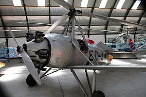
 Cierva C.19 Mk. IVP of the Spanish Air Force in the Museo del Aire in Cuatro Vientos (registration number EC-AIM) |
|
| Type: | Gyroplane |
| Design country: | |
| Manufacturer: | |
| First flight: |
1929 |
| Number of pieces: |
28 (built to order by Avro) |
The Cierva C. 19 was a gyroplane that was built in the late 1920s in 28 copies in Great Britain by AV Roe and Company on behalf of the Cierva Autogiro Company in Hamble .
history
development
At the end of 1928, after Armstrong Whitworth took over Avro , the Avro design office moved from Hamble to the main factory in Manchester. Some of the Avro production remained in Hamble in order to complete the production of the machines on schedule. This included the construction carried out on behalf of Cierva and the construction of the C.19. Since the Avro team was signed by Cierva, the machines were given Avro works numbers, but the only gyroplanes built here did not have Avro design numbers (type numbers). The C.19 was the first gyroplane from the Cierva Autogiro Company that could be produced in significant numbers.
C. 19 Mk. I
Of the three Mk.I series machines built (registration G-AAGK, G-AAGL, G-AAHM), the first had its maiden flight in July 1929. The C.19 Mk. I was intended for commercial use from the start, while the previous models from Cierva were more likely to be seen as experimental aircraft. The C.19 was also the first gyroplane whose fuselage was consistently designed from the outset according to the special requirements of such an aircraft. All previous machines used conversions of fixed wing aircraft. The Mk. I had an 80 hp Armstrong Siddeley Genet II installed in the nose of the fuselage to generate the propulsion . However, this engine was not sufficient, so that the Mk. I had to be viewed as clearly underpowered. However, praised for ease of use in flight. At the start, the engine was run up and the propeller downdraft flowing against the raised horizontal tail surface brought the rotor to around 100 to 130 revolutions per minute within 45 seconds, depending on the current wind conditions. After that, however, a taxiing distance of around 30 m was necessary, as a start was only possible from a speed of 150 min −1 .
C. 19 Mk. II
The Mk. II was created by installing the Armstrong Siddeley Genet Major I , which was a little more powerful with 105 hp , but the problem of under-motorization remained. The three copies built received the G-AAKY, G-AAKZ and G-AALA license plates. Cierva transported the first machine in a disassembled state on the White Star Liner RMS Majestic to the USA in August 1929 , in order to demonstrate it to Harold Pitcairn . Cierva flew the G-AAKY daily at the Cleveland Air Races in Ohio, making it the first gyroplane on public display in the United States. Together with further improvements, such as a larger tank capacity, a chassis with greater spring travel and improvements to the rotor hub, the rotor diameter has also been increased to 10.68 m. One machine (G-AAUA) was flown with these improvements to the RAF display on June 30, 1930.
C. 19 Mk. III
The Mk. III was the first Cierva gyroplane that was actually built with six copies in a small series. The second and sixth Mk. III went to the RAF and were given the serial numbers K1696 and K1948. The third machine (G-AAYP) was converted to a Mk. IV.
C. 19 Mk. IV
The third Mk. I (G-AAHM) built served as a prototype for the Mk. IV variant. The Mk. IV (ex Mk. III) with the registration G-AAYP went to the Airplane and Armament Experimental Establishment (A & AEE) as the first rotary wing aircraft to be tested in early 1932 . A total of 15 Mk. IV were built, most of which were sold abroad. The machines were given the designation C.19 Mk. IVP after retrofitting a rotor start clutch and the associated drive shaft, a rotor folding mechanism and the simplified tail unit.
C. 19 Mk. V

With the Mk. V, a completely new type of flight control was used for the first time with the method known as Direct Control . With the samples C.4 , C.10 and C.11 , Cierva had already developed the first solutions for a movable, controlled bearing of the rotor hub, but these were not very successful. The aim was to ensure sufficient stability and control over the flight status even at low flight speeds. With the aerodynamic control devices customary up to that point, whose effectiveness decreased with falling airspeed, landings in crosswinds were also very problematic. On December 16, 1933, Cierva received a British patent on the controllable rotor head he had developed, which formed the basis for all further gyroplane developments. However, David Kay must also be mentioned, who had already developed a laterally tilting rotor head in 1927 and used it for the first time in 1932 on the Kay 32/1 gyroplane he designed .
The first machine in which Direct Control was used was a conversion of the Mk. IV G-ABXP, which became the C.19 Mk. V. At first she only flew with a large rudder for directional stability, but without elevator and wings. After the first flight attempts in Hamble, the Mk. V also received a board-like horizontal stabilizer under the stern. The movable rotor head was initially controlled with a standard joystick via bumpers, but afterwards only a hanging joystick connected directly to the hub ( English elephant trunk , German: "elephant trunk") was used.
The public presentation of the new machine was on November 14, 1932 in Hanworth.
Focke-Wulf building under license
In 1931, Henrich Focke , technical director and co-owner of Focke-Wulf Flugzeugbau , decided to acquire a license from Cierva Autogiro to build a gyroplane , with the realization of stable- safe flight playing a major role. The basis for the license of the Focke-Wulf C.20 was the C.19 Mk. IV, the first version in which the motor could be used to turn the rotor via a coupling shaft. As this enabled the rotor to be brought to full speed even when the vehicle was stationary, the Mk. IV can be seen as a real quick starter. On the first flight with Rawson at the controls of the C.20 in Bremen in June 1932, Juan de la Cierva was also present. However, fewer than ten other machines were built.
construction
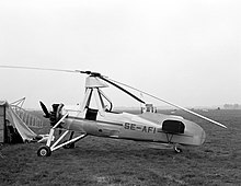
The two-person crew was accommodated on seats in tandem. The four-blade rotor (Mk. IV: three-blade rotor) had a diameter of 9.15 m. The blades of the Mk. I to Mk. III were braced towards the stub axle of the rotor in order to limit the downward flapping movement. The C.19 received two important technical developments: on the one hand, the thrust line of the engine was shifted downwards by about 5 degrees compared to the longitudinal axis of the fuselage, and the axis of rotation of the rotor was also inclined by 3 degrees to the starboard.
The C.19 Mk. I to III had a so-called "box tail" (similar to the box wing design), also referred to by Cierva as the Scorpion tail . The two horizontal surfaces could be set almost vertically in order to divert the outflow of the propeller upwards to the rotor. The first attempts with this tail unit design were carried out with the Loring C.12 . This tail unit, which was initially also used on the Mk. IV, was later replaced by a conventional tail unit, as a coupling shaft leading from the rear of the engine to the rotor head was retrofitted to crank the rotor before take-off.
Technical specifications
after Ord-Hume
| Parameter | Mk. I | Mk. II | Mk. III | Mk. IVP | Mk. V |
|---|---|---|---|---|---|
| crew | 2 | ||||
| length | ? m | 5.39 m | 5.57 m | 6.05 m | |
| Span of the wing |
6.25 m | 6.41 m | without wing | ||
| Rotor diameter | 9.15 m | 10.68 m | 10.37 m | 11.29 m | |
| Rotor speed | 140 to 160 min -1 | 180 min −1 | 125 min −1 | 180 min −1 | |
| height | 3.36 m | 3.05 m | 3.36 m | ||
| Empty mass | 363 kg | 431 kg | 436 kg | 488 kg | 427 kg |
| Max. Takeoff mass | 590 kg | 636 kg | 704 kg | 658 kg | |
| Top speed | 136 to 152 km / h | 131 to 152 km / h | 163 km / h | 160 km / h | |
| Cruising speed | 112 to 128 km / h | 112 km / h | 120 km / h | 144 km / h | 131 km / h |
| Range | 288 km | 480 km | 300 km | 368 km | |
| Engine | an Armstrong Siddeley Genet II (80 hp) |
Genet Major I (105 HP) | |||
Preserved copies
A C.19 Mk.IVP (EC-AIM) is exhibited in the Museo del Aire in Cuatro Vientos (Spain).
See also
literature
- Arthur WJG Ord-Hume: Autogiro - Rotary Wings Before the Helicopter , Mushroom Model Pub., 2009, ISBN 978-83-89450-83-8 , p. 75 f., P. 289
- Bruce H. Charnov: From Autogiro to Gyroplane , Praeger Publishers, 2003, ISBN 1-56720-503-8
- TR Hiett: Cierva's rotating wings . In: AIR Enthusiast July / August 2003, pp. 26–31
- AJ Jackson: Avro Aircraft since 1908 , Putnam, 1965, 2nd edition 1990, ISBN 0-85177-834-8 , pp. 455-456
- Otto E. Pabst: Kurzstarter und high-flyer (Die deutsche Luftfahrt Volume 6) , Bernard & Graefe Verlag, 1984, ISBN 3-7637-5277-3 , pp. 33-43
- Planes from A – Z - Cierva Autogyros . In: AERO - The illustrated compilation of aviation. No. 51, pp. 1424 ff., 1984, Marshall Cavendish.
Web links
Individual evidence
- ^ Report on the use of the first gyroplane in South Africa
- ↑ Charnov, 2003, p. 117 f.
- ↑ Otto E. Pabst, 1984, p. 34
- ↑ Arthur WJG Ord-Hume, 2009, p. 289


