EMF measurement
EMF measurements are measurements of electromagnetic fields with probes or sensors. Even if they are made with different properties, these probes can usually be thought of as normal antennas. In order to obtain accurate and reliable measurements, the probes do not have to interfere with the electromagnetic field and avoid clutches and reflections. EMF measurements are becoming increasingly important and used in a myriad of contexts to accurately determine the non-ionizing emissions to which people and the environment are exposed. According to a first classification , one can distinguish between two different types of EMF measurements:
- Broadband measurements made with a broadband probe that can identify signals within a broad frequency band and is usually made up of three different detector diodes;
- Selective measurements in frequency; in this case the measurement system consists of an antenna and a selective receiving device or a spectrum analyzer, with which one can precisely control the desired frequency band.
The probes also differ according to the type of measurement you want to take.
Ideal isotropic measurements
In this case, the EMF measurements are obtained by an electric (E) or magnetic (M) field sensor, which can be isotropic, mono-axial, passive or active. An omnidirectional and mono-axial sensor is a device that detects the electrical (in this case a sensor equipped with a short dipole) or the linearly polarized magnetic field in a certain position.
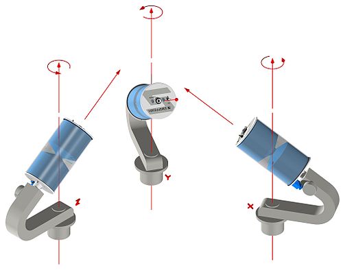
Since a mono-axial probe is used, three different measurements must be made; one for each orthogonal direction in which the axis of the sensor is set.
For example, one can use a probe to survey the component of the electric field that is parallel to the direction of one's own axis of symmetry . If, under these circumstances, E is the size of the incident electric field and θ is the size of the angle between the sensor axis and the direction of the electric field, the signal is of the type | E | cos θ (right). So one can express the total size of the field in the following form:
or for the magnetic field
Since the total size of the field can be determined by three measurements, a tri-axial probe simplifies the measurement procedure, because in this case the position of the sensor does not have to be changed; Since the geometry of the device consists of three independent broadband sensors that are set up in orthogonal directions, the position of the sensor does not have to be changed. The output of each individual measuring element is calculated in three consecutive periods on the assumption that the field components do not change over time.
Active and passive sensors
Active sensors are devices that contain active components; normally the active sensors allow more accurate measurements than the passive ones. The energy received from a passive antenna or sensor is relayed to an RF connector. This signal is then measured by the spectrum analyzer. It should be noted, however, that the properties of the field could change, especially with a nearby field.
A more efficient solution, however, could be to transfer the components of the electric or magnetic field picked up by the probe to an optical fiber.
The basic system component, which consists of an electro-optical receiving antenna, can transmit the components of the electric or magnetic field, which are then made available as an electric signal for an opto-electronic converter, to an optical fiber.
The optically modulated transmission medium is transmitted through a connection with an optical fiber to a converter which takes out the modulating signal and converts it into an electrical signal. It is transmitted with a standard 50 Ω RF cable.
Isotropic deviation
In the EMF measurements, the isotropic deviation describes the accuracy of the field intensities regardless of the probe orientation. If the field in an X, Y, Z orthogonal configuration can be given in the following form:
A sufficient condition to make this statement form true for each triple of the orthogonal coordinates (X, Y, Z) is obtained if the probe radiation diagram approaches the short dipole diagram as closely as possible (?). The diagram of this short dipole can be expressed in the following form:
- ,
where A is a function of frequency. The difference between the ideal radiation diagram of the short dipole and the real one of the probe is identified by the term "isotropic deviation".
Web links
- Clampco Sistemi Isotropic antenna AT3000
- Clampco Sistemi Electric field probe FP2000
- Clampco Sistemi EMF measurement antennas
- EMC Zurich
- The 16th International Zurich Symposium and Technical Exhibition on Electromagnetic Compatibility - EMC Zurich 2005


