
Variable capacitor

Variable capacitors (Varkos) are electrical capacitors whose capacity can be continuously and reproducibly adjusted within defined limits.
They are predominantly in filters and oscillators , for the tuning of transmitters or receivers , and for impedance matching used.
There are mechanically and electrically variable capacitors.
The mechanically variable capacitors belong to the passive components and are divided into variable capacitors , which are designed for transmitter tuning for frequent and repetitive actuations and trimming capacitors , which are designed for one-off or infrequent actuations for fine tuning.
Most of the designs of mechanically variable capacitors only have historical significance. Nowadays (2017) still manufactured designs are u. A. Trimmers with ceramic or plastic film dielectric for small powers, tube-spindle trimmers for high frequencies and variable vacuum capacitors for devices with higher powers such. B. in MRI scanners.
With smaller powers, adjustable capacitance can also be achieved with electrically variable capacitors ( capacitance diodes , also called varactors or varicaps). Capacitance diodes are active components and use the property of a pn junction to change its capacitance depending on an applied DC voltage. In addition to capacitance diodes, electrically variable capacitors also include dielectrically variable capacitors, for example BST varactors, digitally variable capacitors and electrically variable RF - MEMS capacitors
Due to the small dimensions of the varactor diodes, they are not only suitable for radios, but also for higher frequencies up to several 100 GHz. You will u. a. Used in filters for frequency selection from around 1 MHz in stationary and mobile receivers, but increasingly being replaced by digital signal processing.
Basics and advice
Mechanically variable capacitors
The mechanically variable capacitors are divided into
- Rotary capacitors ( Tuning capacitors ), called rotary capacitors for short, are tuning capacitors that are designed for frequent and repetitive operations, e.g. B. for manual tuning in radio sets or motor-controlled automatic control of a transmitter frequency and in
- Trimming capacitors ( Trimmer capacitors ), also called trimmers, are designed for one-time or infrequent operations for fine-tuning of resonant circuits and are actuated during the initial installation and, if necessary after repairs for adjustment of resonant circuits or filters. Trimmers are usually connected in parallel to the variable capacitor in a tuning circuit for fine tuning.
The principle of the plate capacitor applies to the mechanical variable capacitors, the capacitance of which is greater, the larger the electrode area and the relative permittivity and the smaller the distance between the electrodes.


The capacitance value of mechanically variable capacitors can be influenced in three different ways
- Change of the capacitively effective overlapping electrode areas
- Change of the electrode distance to each other or by
- the choice of a suitable dielectric material.
- Schematic representations of the possibilities of mechanical capacity change

Rotary capacitor, change in capacitance by changing the electrode overlap in rotating metal plates

Immersion trimmer, change in capacitance by changing the electrode overlap when immersing concentric cylindrical electrode caps

Tube trimmer, multiturn trimmer, capacity change by changing the electrode overlap when screwing a metal pin into a stator metal sleeve

Squeezer, change in capacitance by changing the distance between the electrodes


The desired change in capacitance in the majority of the adjustable capacitors still manufactured today, both in the case of the rotary and trimmer capacitors, is based on the change in the capacitively effective overlapping electrode area without changing the distance between the electrodes. The capacitance and dielectric strength and quality factor of these capacitors also depend on the dielectric used. In the course of time the following materials were used:
| Dielectric material |
relative permittivity ε r at 1 kHz |
Dielectric strength in kV / mm |
|---|---|---|
| vacuum | 1 | 20 ... 500 |
| air | 1 | 2… 5 |
| Sulfur hexafluoride (SF 6 ) | 2 | 8th |
| mica | 7th | 25… 200 |
| Ceramic class 1 | 6… 200 | 20th |
| Ceramic class 2 ( barium strontium titanate ) |
100 ... 1000 | 25th |
| Sapphire (Al 2 O 3 ) | 8.9 ... 11.1 | 700 ... 1000 |
| Hard paper | 4th | 20 ... 80 |
| Polyester (PET) | 3.3 | 25… 580 |
| Polycarbonate (PC) | 3.0 | 35… 535 |
| Polyethylene naphthalate (PEN) | 3.0 | 25 ... 500 |
| Polypropylene (PP) | 2.2 | 100 ... 650 |
| Teflon (PTFE) | 2.1 | 100 ... 250 |
- Measurement of the capacitance of a variable capacitor

C min = 29 pF
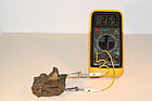
C = 269 pF

C max = 520 pF


Electrically variable capacitors
Electrically-variable capacitors , and varactors ( varactor ) composed not of the passive components , but with the active components and use the properties of semiconductor technology to obtain a reproducible variable capacitance. The electrically variable capacitors include:
- Capacitance diodes ( varicap diode ) in which electrically influenced by change of the space charge region can be varied, the electrode spacing and hence the capacitance.
- Dielectric variable capacitors ( dielectric varactors ), for example integrated variable BST capacitors or BST varactors ( BST varactors ), the specialty of which is the dielectric made from the ferroelectric material barium strontium titanate (BST) . BST has a relatively high relative permittivity that depends on the field strength in the dielectric. The capacitance of the BST varactors is therefore dependent on the applied voltage.
- Digital variable capacitors ( Digitally Tunable Capacitors (DTC) ) are arrangements of a plurality of integrated capacitors in integrated circuits of different semiconductor technologies that can be / serially connected in parallel across digitally coded switch so that achieved a desired capacitance value for tuning a resonant circuit or Filters is needed.
- Electrically variable RF - MEMS capacitors ( Tunable RF MEMS capacitors ), in which the force is used with which oppositely charged movable electrodes attract each other when a voltage is applied, in order to generate electrically adjustable capacitance values.
Electrically variable capacitors are mainly used in mobile receiving devices with lower power for frequency selection for all commercial and industrial channels . Their application extends into the range of very high and very high frequencies up to a few 100 GHz.
history
The first decades
- Detector receiver
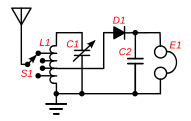
Directly coupled detector-receiver circuit with a switched coil (L1) and a tuning capacitor (C2) for impedance matching
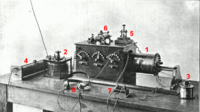
Early detector receiver with adjustable antenna coupling transformer (1) and two tuning capacitors (2), (3)


With the discovery of the wireless transmission of electrical spark discharges by Alexander Popow in 1895 and its further development by Guglielmo Marconi from 1896, which led to the development of wireless telegraphy , it became necessary to keep both the transmission and reception frequency in the systems and devices used in tight To be able to set limits. The frequency that was generated with an oscillating circuit consisting of a coil and a capacitor could be influenced either by changing the inductance or by changing the capacitance of the oscillating circuit. The latter was made possible by Dezső Korda in 1892 with the invention of a rotary capacitor, the capacity of which was determined by an adjustable overlap of the electrode surfaces . This first adjustable capacitor worked with rotor electrodes on a rotating shaft , which could be screwed like a comb into a package with stator electrodes to change the capacitance. These variable capacitors were improved by Adolf Koepsel from 1901 and introduced into wireless telegraphy at Siemens .
- Variable capacitors from the early days of broadcast technology
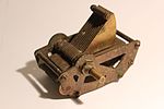
Variable capacitor from the 1920s

Variable capacitor in an open Pertinax housing with phenolic resin paper as the dielectric

Variable capacitor in a closed housing for protection against dust and moisture


.jpg)

The audio tube , invented in 1906 by Lee De Forest , was the first component in electrical engineering for a functioning signal amplification. After the invention of the oscillator circuit with an electron tube in 1913 by Alexander Meißner and the further inventions based on it, the actual development of radio technology began .
The first radio receivers at the beginning of the 20th century were straight-ahead receivers , which were mostly equipped with switched coils to set the frequency. However, variable capacitors with an air dielectric were also used in these first detector receivers. In the following years, these variable capacitors took over more and more of the tuning of the respective receiver circuit and thus replaced the tuning of the transmitter using movable or switched coils. They were used in the vast majority of radios until well after World War II . Rotary capacitors were also used on the transmitter side to set the transmission frequency.
Rotary capacitors require a relatively large amount of space because of the necessary plate spacing, required a mechanically stable construction and were expensive. Cheaper and smaller solutions were sought. This could be achieved by introducing other dielectrics. Mica was used as a dielectric for the so-called block capacitors and has a relative permittivity that is 7 times higher and a dielectric strength about 10 times higher than air. So it made sense to use mica to reduce the size of the variable capacitors. However, this solution soon turned out to be too expensive because mica as a natural product had to be laboriously processed, was expensive and caused mechanical problems. Instead of mica, rotary capacitors with phenolic resin-impregnated hard paper as a dielectric, mounted between Pertinax plates, were developed as early as the 1930s , which quickly became popular in inexpensive devices.
With the development of receiver technology from the straight-ahead receiver to the superheterodyne receiver , also called superheterodyne receiver, or superheterodyne for short, the technology of which was developed during the 1st World War, further variable capacitors were used from around the mid-1920s, depending on the number of amplifier stages in the "super" Coordination of the individual circles required. For this purpose, the individual variable capacitors were simply provided with a common shaft in order to achieve uniform coordination. A "four-circle model" could therefore contain four rotary heads with a common shaft.
- Rotary capacitors for multi-circuit receivers

Block diagram of a dual circuit heterodyne receiver

Double rotary capacitor with two rotor / stator packages on one shaft with which two amplifier circuits can be evenly tuned

Double rotary capacitor combined with two trimmer capacitors for fine tuning of the intermediate frequency


In addition, additional variable capacitors were required, which had to be suitable for a one-time adjustment process for setting or "trimming" the intermediate frequency of the oscillator circuit. Rotary capacitors with their mechanically very complex construction were oversized for this. These trimmer capacitors had to be very finely adjustable, but the mechanics only needed to be moved once. This resulted in the mostly mechanically much simpler and cheaper designs of the "trimming capacitors", which were available in a large number of designs and are still available today.
- Various trimmer capacitors

Different designs of trimmer capacitors with different dielectrics

Vernier capacitor (squeezer) with mica dielectric according to Manfred von Ardenne
"Immersion trimmer" with concentric cylindrical electrode caps


Variable capacitors with adjustable electrode spacing, Vernier capacitors or also called "squeezers" were popular among radio amateurs in the early years of radio engineering, but they are rarely used industrially because of their inaccuracy in setting.
In the 1930s and 1940s, the requirements for the variable capacitors on the transmitter side increased with increasing transmitter power. As a result, the resonant circuit voltage continued to rise. The variable capacitors with air dielectric for broadcasting stations got bigger and bigger. New solutions with other dielectric materials have been developed in order to get back to smaller dimensions, for example encapsulated variable capacitors with insulating oil as the dielectric. However, variable vacuum capacitors or variable capacitors filled with the protective gas SF 6 , which were provided with an electrode construction based on the immersion trimmer principle, then prevailed. The vacuum capacitor was invented by Nikola Tesla as early as 1896 to improve the quality of capacitors and for the suitability of high currents and high frequencies. This idea to also use it for variable capacitors was realized in 1942.
After the 2nd World War
The development of variable capacitors after World War II is characterized by rapid developments in all fields of technology involved. For example, new plastics and ceramics were developed that made new dielectrics and housings possible, which pushed miniaturization forward. In particular, the development of variable capacitors based on semiconductors in combination with new analog and digital circuits has meant that most applications of the mechanically variable capacitors could be replaced. On the other hand, with increasing industrialization, there were always new applications for mechanically variable capacitors, so that these still have a wide variety of applications in devices with high quality requirements.
After the war, a boom began in all countries in the field of radio technology and later television technology. In superhet radios for the AM reception of KW , MW and later for the FM reception of VHF transmitters, rotary and trimmer capacitors were indispensable for station setting. In addition, there was miniaturization in the form of car and transistor radios , which also led to new encapsulated designs with air / foil dielectric in the mechanical Varkos.
- Construction of transistor radios with variable capacitor transmitter setting from the 1960-1970s
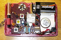
Open AM medium wave transistor radio from 1960 with two circles, recognizable by the double rotating capacitor mounted in the middle, which was operated by means of a turntable on the front of the radio for setting the station.

Open AM long and medium wave transistor radio with a side-operated variable capacitor for transmitter tuning


The reception of television stations expanded the frequency range to be received, which in radio went into the VHF range, to include the ultra-short wave range ( VHF band I and VHF band III ). In the post-war period there were initially only 5 channels that were available with a fairly stable frequency. Therefore, the transmitter setting was implemented with several permanently calibrated receiving circuits as rotary switches that function as a drum channel selector. The adjustable coils required for the respective receiving channel were located on the circumference of a drum. Rotary capacitors, which were still used in the first television sets in the 1940s, were not necessary here - only a trimmer operated via a hollow shaft was used for fine tuning. In the 1950-1960s, the drum channel selectors were replaced by tuners in which the station was selected using buttons. In the first tuners, only trimmer capacitors were required for fine tuning.
The replacement of mechanically variable capacitors with electrically variable capacitors began with a new development in the field of semiconductor technology. 1961 was varicap diode invented. Based on this new component, Philips K.-H. Copper 1967, a first "voting circuit arrangement having a switching diode" which a voltage controlled oscillator (VCO voltage-controlled oscillator ) contained. From 1969 this development resulted in an electrical receiving and tuning circuit for the selection of radio stations and television channels, called tuners, which set a desired station electrically with the help of varicap diodes and a VCO implemented with it. This made it possible to build tuners for radio and television sets, the station selection of which managed without mechanical rotary and trimmer capacitors or mechanical wave switches and channel selectors, which replaced the significantly more expensive mechanical solutions in the following years.
- Construction of tuners with varicap diodes from the 1980-1990s

Circuit board of an AM and FM radio tuner with varicap diodes marked in red

Circuit board of a UHF and VHF television tuner with varicap diodes marked in yellow


In parallel to the development of new components such as varactor diodes and integrated circuits in the 1950-1960s, new circuit technologies were developed for radio and television sets. The frequency adjustment by means of a quartz oscillator in a VCO and an electronic phase-locked loop ( PLL, phase-locked loop ) extending the potentiality of the tuner and provided a high electrical long-term stability. Starting in 1969, PLL circuits from companies such as Signetics , which was taken over by Philips in 1975, were offered as ready-made integrated circuits. This once again greatly simplified the effort for a tuner and made it cheaper. These tuners, which can be operated at the push of a button or later by remote control, without additional mechanical balancing elements, ultimately made mechanically variable capacitors in the receiving section of radio and television receivers obsolete.

In the period that followed, the initially analog circuit technology was gradually replaced by digital circuits in the entire field of radio and television technology. The development of the so-called "one-chip ICs" can be seen as milestones in this development towards digital technology. As early as 1983, Philips brought the first “One Chip” VHF radio IC TDA 7010 onto the market, which according to the data sheet only required an external trimmer capacitor. This circuit contained a receiver based on the superimposition principle for receiving 1.5-110 MHz at a very low intermediate frequency of 70 kHz and was therefore initially unsuitable for stereo reception.
At the latest after the development of the first “Ultimate One Chip TV UOC”, TDA 935X / 6X / 8X, the first IC for flat screen televisions, which came onto the market in 1996, this development, which managed without mechanical components, was on the market enforced. Today's television and radio receivers have tuner and digital signal processing (DSP) ( Digital Signal Processing ) no mechanical capacitive tuning elements more.
Types of historic tuning capacitors
Variable capacitors

Rotary capacitors with an air dielectric are the best known of the variable capacitors and are still regarded today as a typical design of these components. They were used to receive AM and FM radio broadcasts from the 1950s to the 1970s. Nowadays (2017) they no longer have any industrial significance, but are listed here because of their earlier significance and clarity.
Rotary capacitors have a stator , a package of fixed, spaced-apart metal plates and an equal number of centrally placed metal plates on a shaft , a rotor and work with air as a dielectric. By turning the shaft, the electrodes are turned into one another in a comb shape, which changes the overlapping area of the capacitor and thus the capacitance. The capacitance values of variable capacitors were usually between 15 and 600 pF. Air rotary capacitors can be manufactured with plate spacing in steps according to the required dielectric strength with about 1000 <V to 11,000 V.
The mechanism of variable capacitors is usually very stable. The shaft of the rotor is usually fastened to the housing with ball bearings , which means that the shaft can be accurately axially fixed without mechanical clearance. An axial play would lead to changes in capacitance and the risk of a short circuit. The angle of rotation of a rotary capacitor is usually 180 degrees.
The stator of variable capacitors is insulated and attached to the housing frame and provided with separate soldering connection lugs. The rotor is electrically contacted via a sliding contact. Since the rotor protrudes further out of the circuit, it is normally connected to ground so that external influences cannot influence the capacitance ("hand sensitivity"), which would make exact tuning impossible.
Plate cuts
The electrode plates of the rotor of variable capacitors can be shaped differently in order to influence the way of tuning. For a linear course of the change in capacitance with the angle of rotation, the rotor electrodes are designed to be circular. A user-specific curve of the change in capacitance can also be achieved through a special, logarithmic shape of the rotor electrodes. The plate shape can be designed, for example, in such a way that the change in capacitance corresponds to a linear wavelength adjustment or a linear frequency adjustment. This means that the transmitter setting can be adapted to the requirements of the respective device.
- Plate sections of variable capacitors

circular plate section for linear capacity curve

logarithmic plate section for wave-linear curve progression

logarithmic plate section for frequency-linear curve progression


Rotary capacitor designs that are rarely used are butterfly rotary capacitors and differential rotary capacitors.
- Plate sections of variable capacitors

Plate section of butterfly rotary capacitors

Plate section of differential rotary capacitors


With the butterfly variable capacitor, the plate section of the rotor electrodes is designed similar to a butterfly wing pair. The vanes rotate evenly into two stator packs that are arranged on the side and mechanically separated from one another. Since the rotor of the butterfly variable capacitor is only connected capacitively and not electrically, this design avoids any contact problems that may arise with the sliding contacts that are normally used.
The differential variable capacitor also contains two laterally opposite stator packs, which are, however, electrically separated from one another. The stator electrodes of both packages are cut roughly in a semicircle. The rotor package, which here is mostly designed strictly semicircular, then rotates out of one stator package and into the other when it is actuated. As the capacity decreases on one side, it increases on the other. Differential variable capacitors are used, for example, for the adjustable distribution of an RF signal to two different circuit branches, for setting coupling degrees between circuit stages or for impedance matching in pi elements .
Multiple versions
Multiple variable capacitors are used if the frequencies of several oscillating circuits in a receiver are to be changed simultaneously via a drive. They have several electrically separated stators into which an equal number of mechanically coupled rotors can be rotated via a common shaft. This ensures good synchronization properties. Multiple rotary capacitors are available with up to four coupled individual capacitors, which are adjusted with a common shaft.
Trimmable rotary capacitors

The outer, mechanically accessible rotor disk of variable capacitors is often slotted (feathered) so that individual segments are created. By bending individual or several segments of this feathering (in the picture by means of a screw), a certain adjustment of the angle dependence of the variable capacitance can be achieved with these rotary capacitors, whereby B. the synchronization between the oscillator circuit and the input circuit can be improved. With heterodyne receivers, this synchronization is important because of the constant distance between the receiving frequency and the oscillator frequency.
Drives
If it is necessary to set the transmitter at very closely spaced transmission frequencies, the normal rotation angle of 180 degrees of variable capacitors can be too coarse for manual tuning. In such cases, the drive takes place via a backlash-free reduction gear. There were various versions:
- Spur gear with a longitudinally divided, spring-loaded gear
- Cable pull (in principle a belt drive, but with a cable section and tension spring fixed relative to the scale display)
- Friction wheels, for example a sheet metal disc clamped between two discs on the drive shaft at the edge
- Planetary gear , which is formed by a tensioned ball bearing (output: ball cage); This type allowed an alternating reduction ratio with a driver - after just under one revolution, the driver reduced the reduction from 2: 1 (fine adjustment) to 1: 1 (overdrive) by turning the cage directly.
Correction capacitors

Correction capacitors with an air dielectric, also known as variable capacitors, were a special design similar to variable capacitors . They had a mounting plate on which the stator package was attached and were intended for central assembly. The rotor was connected via a grinder with soldering lugs attached to the side. The mechanics were very stable, the drive shaft was mounted in the carrier plate with a ball bearing and was also designed for repeated operations. The correction capacitors were available in different plate sections (linear, logarithmic) as well as a butterfly and a differential version. In transmitters with a lower output, they were used for constant, mostly manual fine-tuning of the transmission or reception frequency, for example in military equipment or in measuring standards for calibrating measured variables.
Correction capacitors have been replaced by air plate trimmers in the course of development , if a mechanical solution is implemented at all.
Rotary foil capacitors


For the further development of the variable capacitors for manual transmitter tuning, it was necessary even before the Second World War to reduce the dimensions and the manufacturing costs. For this purpose, the construction of the rotary cos was placed between two Pertinax plates and a hard paper disc was placed between the rotor and stator plates . Due to the associated higher dielectric strength compared to a pure air dielectric, the electrode plates could be brought together much more closely and these Pertinax film rotary capacitors were significantly smaller than the usual rotary capacitors, but served the same purpose. They were the forerunners of the later rotary film capacitors.
With the development of plastics in organic chemistry after World War II, the Pertinax / hard paper construction was replaced by the more modern and durable plastics. In addition, the stator-rotor construction was also encapsulated to protect it against contamination. The result was the film rotary capacitors used especially in portable transistor radios for tuning stations, the further advantage of which was that they had solder pin connections in a standardized grid dimension and were therefore suitable for automatic assembly.
Single-foil rotary capacitors with only one stator-rotor package were used in inexpensive single-circuit devices for tuning and for setting the feedback. Multiple-film rotary heads have several rotor / stator packages on a common shaft. They were put together, partly together with trimming capacitors, in a housing to form combination rotary capacitors. They were safe to use and since the trimmers were accessible from above on the circuit board, they could be adjusted automatically after production.
These rotary film capacitors for setting transmitters in radio receivers no longer play a role in industry today.
Variable SF 6 shielding gas capacitors
In SF 6 protective gas capacitors ( Compressed gas variable capacitors ) there is the inert gas sulfur hexafluoride (SF 6 ) with a gas pressure of 3 bar to 7 bar as a dielectric. They are similar to the diving trimmers described here . The rotor-stator-electrode package is built into a hermetically sealed housing that is filled with the protective gas SF 6 , the angle of rotation is more than 360 °.
SF 6 shielding gas capacitors were used, among other things, in medium and long-wave transmission systems with higher power to match the impedance of the transmission output stage to the antenna. Usual values for this application are adjustable capacitance values from 50 pF to 5 nF with test voltages of up to 80 kV and operating currents of up to 800 A. The adjustment was made in the transmitter system during operation with servomotors.
Due to the better properties of a vacuum dielectric, which leads to a smaller size with the same performance data, variable SF 6 shielding gas capacitors are no longer used for new applications.
Designs of historical trimming capacitors
General

Trimming capacitors, which are only used for initial commissioning and, if necessary, after repairs to adjust a filter or an oscillating circuit, should only be adjusted with an isolating (HF-neutral) tool, usually a plastic screwdriver, as metallic contact would influence the capacitance. It is important for all trimmers that once the capacity has been set, it is not changed by vibrations. This is why the shaft, via which the capacitance value was set, is often fixed with varnish after the adjustment .
Crimp Trim Capacitors
In the mid-1920s, the Vernier capacitor was an inexpensive solution for setting a desired capacitance value by changing the distance between the plates. They were " Squeezer " ( Squeezer called) and were suitable for a one-time adjustment process for adjusting the oscillator circuit. The capacitance of these Vernier capacitors was changed with the help of a set screw on a movable electrode. To avoid short circuits and to increase the capacity, a mica plate was used as a dielectric. This enabled capacity values to be set fairly constant.
A similar trimming capacitor based on the principle of the Vernier capacitor was developed by Manfred von Ardenne in the 1930s , see picture "Rotary capacitors from the early days of broadcast technology" above.
Wire trimmer
Wire trimmers from the early days of receiver technology corresponded in their structure to the ceramic tube capacitors of that time. The inside metallized ceramic tube was provided on the outside with a wire winding soldered to one another instead of a second metallization. This wire could only be unwound but not rewound. They were offered with capacitance values of up to about 570 pF until the end of the 1960s.
Submersible trimmer

Submersible trimmers were developed in the 1930s. They consisted of two concentric cylindrical electrodes of different sizes, which were rotated into one another with the help of a central spindle that carries and contacts the rotor.
The linear movement of the immersed part allowed a first (mechanical) solution ( Philips , around 1930) of a program selector switch to select different transmitters with a set of buttons using preset capacities to which the immersion trimmers were connected in parallel. The disadvantage was the inadequate mechanical accuracy and the geometrically determined linear capacitance curve, which does not comply with the oscillatory circuit laws. This solution lasted until the 1970s, but - like other trimmer designs - was no longer required due to the development of varactor diodes. However, the electrode principle has been retained for variable vacuum and SF 6 shielding gas capacitors.
Ceramic disc trimmer

Ceramic disc trimmer ( Ceramic half-turn trimmer ) have been developed around the mid-1930s. They consist of a ceramic base plate, on whose ground surface a semicircular metallization forms the stator. A rotatable ceramic disc, also ground at the bottom, which has a semicircular metallization on the top of the ceramic, forms the rotor. The ceramic of this rotor and its thickness form the dielectric. The rotor is slotted for mechanical operation. A sliding contact makes contact with the rotor with the corresponding solder connection.
Ceramic disc trimmers were made from class 1 ceramics with a field strength-independent relative permittivity , a linear temperature dependence of the capacitance and a high quality factor . Thanks to these good properties, the expensive mica dielectric could be replaced inexpensively with ceramics.
These disc trimmers, with their precise temperature gradients, became popular balancing capacitors because they contributed to temperature-stable oscillator frequencies. Their basic structure was retained in the SMD trimmers, but the older sizes are no longer used in industry today.
Ceramic pipe trimmer

Ceramic tube trimmers , like the Keraik disc trimmers , were developed in the 1930s. They are a further development of the ceramic tube capacitors, which at the time greatly accelerated the development of radio receivers. In these trimmers, a metal spindle, which is electrically connected to the rotor connection via a contact spring, is screwed into a ceramic tube that carries a metallic outer coating with the stator connection. The changing overlap of the stator and rotor electrodes changes the capacitive area and thus the capacitance of the capacitor. Due to their simple and stable construction, these trimmer capacitors are relatively insensitive to shock and vibration stress.
Ceramic tube trimmers have a layered dielectric made from the ceramic material of the tube and the air gap between the ceramic tube and the metal spindle. To achieve different electrical TK values, different types of ceramics are used, which must be coordinated with the expansion coefficient of the spindle material ( brass , Invar steel ).
Ceramic tube trimmers are free of any microphonic effects . They can be set very precisely due to the effective rotation angle of the spindle, which is a multiple of 360 °.
Air plate trimmer

Air plate trimmers are similar to the correction capacitors described above with a central base, but the rotor is not guided in this base in a ball bearing, but in a metal bush. The rotor guide in the metal bushing is designed for repetitive actuation. The base is usually made of ceramic and on which the stator is attached. The stator and rotor consist of two packages of semicircular metal disks, which are rotated into one another in a comb-shaped manner by actuating the shaft. Air is used as the dielectric. The connections of air plate trimmers are mainly designed as solder pins for a circuit board assembly, but they are also offered with solder lugs.
Air plate trimmers have relatively large dimensions because of the low permittivity of air, but they have a very high insulation resistance and a high quality. They are used in transmitters with lower power for continuous, mostly manual fine adjustment of the transmission or reception frequency or in measurement standards for the calibration of measured variables.
Foil trimmer

In parallel to the development of the film rotary capacitors described above, film trimming capacitors were also developed and used in radio sets in the early 1960s . They are constructed in a similar way to the variable capacitors in which the capacitively effective area is changed, but there is still an insulating and dielectrically effective plastic film between the electrodes.
These trimmers were made with different plastic films for different requirements. For standard applications in home appliances, polyethylene foils (PEN) and polypropylene foils ( PP) were used, and plastic foil trimmers with Teflon foil (PTFE) were also manufactured for professional applications . Maximum adjustable capacitance values were 3.5 to 100 pF.
By using the plastic film dielectric with the higher permittivity and the higher dielectric strength, plastic film trimmers could be made significantly smaller than air trimmers. In addition, they were designed for PCB mounting from the start. The soldered connections, two for the rotor and one for the stator, resulted in a 3-hole attachment that was arranged in a standardized grid dimension. As a result, they had a fixed position in the device and could be automatically equipped and automatically adjusted.
Foil trimmers are nowadays (2017) only rarely used and then used in devices with small quantities.
Types of current mechanically variable capacitors
Rotary capacitors , air plate trimmers and foil trimmers will continue to be manufactured and offered, see #Manufacturers of mechanically variable capacitors .
Nowadays, mechanically variable capacitors are mainly used as SMD components with very small dimensions, as tube trimmers for very high frequencies with a high quality factor or as variable vacuum capacitors for very high outputs.
SMD trimmer


Most of the components used in electronic devices can be surface-mounted. This also applies to mechanically adjustable trimmer capacitors. Today's common SMD trimmers ( SMD half-turn trimmers or SMD single-turn trimmers ) are a further development of the # ceramic disc trimmer . They have a ceramic base plate, which, however, has a layered structure, similar to ceramic multilayer capacitors ( MLCC ). The stator is a semicircular metallized layer within the monolithic ceramic plate. This distinguishes them from ceramic disc trimmers, where the stator metallization is on the ceramic. The rotor electrode is a rotatably mounted metal disk with a semicircular profile that is pressed onto the base plate due to the design. Because the metallization lies as a layer in the ceramic base plate, the ceramic material lying above it, the dielectric, can be kept very thin, whereby a higher capacitance can be achieved. The effective angle of rotation is z. B. 80 °, the capacity depends linearly on the angle of rotation.
Ceramic SMD trimmers are offered with class 1 ceramics with different temperature coefficients. You can use it to compensate for temperature-dependent deviations in the frequency source. They are suitable for frequencies up to about 6 GHz. Capacitance values up to around 40 pF are offered.
The smallest SMD trimmers are available in sizes 1.5 × 1.7 × 0.9 mm. They have a footprint that is comparable to the well-known "0805" housing (2.0 × 1.25 × 1.00 mm) of MLCC or tantalum capacitors. SMD trimmers for wave soldering are encapsulated in order to avoid contamination during the soldering process. Trimmers for reflow soldering can be protected a little more simply.
SMD trimmers are required, for example, in LC circuits to adjust and compensate for changes in capacitance. They are still used in crystal oscillators to pull the oscillator frequency. Further applications are the frequency compensation of voltage dividers and the adjustment of capacitive distance sensors.
SMD trimmers can be found in mobile phones, remote-controlled access systems, surveillance cameras, DVD devices and burglar alarms.
SMD laser trimming capacitors

In order to avoid mechanical balancing, SMD laser balancing capacitors ( LASERtrim® RF Tuning Capacitors ) were developed, the capacitance of which can be adjusted by means of a laser by specifically burning away parts of an open electrode.
These laser trimming capacitors are similar to multilayer ceramic chip capacitors. The openly accessible metallization of the top electrode can be vaporized step by step with the help of a laser beam. This allows a capacitance value that starts at around 20 pF, depending on the type, to be set precisely down to around 0.5 pF.
The quality factors (Q) of these balancing capacitors depend on the type of ceramic used and are in the range between 60 and 600. The sizes of these SMD chip designs range from 0603 to 1210. They can therefore be equipped with conventional pick-and-place machines become. Another advantage of these SMD laser balancing capacitors is that they do not have to be protected against contamination from any fluxes that may be used and are also insensitive to mechanical loads such as shock or vibrations.
With this adjustable capacitance range, the SMD laser balancing capacitors are used for balancing purposes in oscillators and frequency filters as well as for impedance matching of antenna circuits for frequencies from 100 MHz to 2 GHz, for example for WLAN , cable modems and RFID cards.
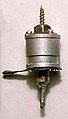
Pipe trimmer

Tubular trimmers ( tubular trimmers or multiturn trimmers ) consist of a tube made of insulating material that has a metal sleeve on the outside as a stator with the stator connection. The rotor, a metal spindle that is electrically connected to the rotor connection via a contact spring, is screwed or pushed into the tube. The changing overlap of stator and rotor, the electrodes, changes the capacitive area and thus the capacitance of the capacitor. They can be (due to the effective angle of rotation of the spindle, which is a multiple of 360 degrees (multiturn) multiturn ) set very precisely. Due to their simple and stable construction, these trimmer capacitors are relatively insensitive to shock and vibration stress.
A similarly designed package for applications in the high GHz range is the so-called piston trimmer ( Piston trimmer )
Various tuning screws made of metal or a dielectric are available for microwave applications up to 100 GHz. Tube trimmers have a layered dielectric made up of the dielectric material of the tube and the air gap between the tube and the metal spindle. The quality of the capacitor and the temperature coefficient (TC value) are mainly determined by the dielectric material, but can be influenced by the spindle materials used, such as brass or invar steel, and their coefficient of expansion .
Tube trimmers are lined on the inside of the stators with the following dielectric materials:
- Air pipe trimmers with an epoxy spacer are suitable for frequencies up to around 1.5 GHz and a test voltage of 500 to 2000 V.
- Ceramic tube trimmers are suitable for frequencies up to around 1.5 GHz and a test voltage of 500 to 2000 V and can be produced with different class 1 ceramics for adapted temperature coefficients
- Teflon pipe trimmers are suitable for frequencies up to around 5 GHz and test voltages up to 20,000 V.
- Glass pipe trimmers have higher capacitance values of up to 120 pF with test voltages of up to 2500 V.
- Quartz pipe trimmers have a very high quality factor
- Sapphire pipe trimmers use aluminum oxide (Al 2 O 3 ) as a dielectric, a material that is characterized by a very high quality factor and a very low temperature coefficient. They are suitable for frequencies up to 10 GHz.
Tube trimmers in the VHF, UHF and microwave frequency range are used in radar devices , in aerospace, in military communication devices, as well as in medical and industrial devices and systems. They are used to adjust the frequency of oscillators and filters. They are offered in different connection versions for PCB or chassis mounting.
Variable vacuum capacitors

Are provided for the comparison of stations of higher high-frequency power, the mechanically adjustable variable vacuum capacitors ( variable vacuum capacitors ). As a dielectric, they have a vacuum with a gas pressure of 10 −3 … 10 −7 mbar. The low impact ionizability of air molecules in a high vacuum results in the very high dielectric strength of vacuum capacitors, which is given on average at around 40 kV / mm. Compared to capacitors with an air dielectric or capacitors filled with the protective gas SF 6 , they can be made much smaller with the same performance data. The smaller design and the low dielectric losses in the vacuum also mean that the ohmic losses of the capacitor, which are reflected in the ESR or in the quality factor, are very low. As a result, variable vacuum capacitors have a very high current carrying capacity.
Variable vacuum capacitors are structurally similar to the # diving trimmers described above . They have a stator made of cylindrical electrodes with usually several cylinders mounted on a base plate. The rotor, which also consists of cylindrical electrodes of smaller diameter, is screwed into the cavities of the stator cylinder with the help of a thread on a central axis. In order to maintain the vacuum during the adjustment process, the screw thread of the rotor is enclosed within the housing with a hermetically sealed metallic bellows-type sleeve. The electrodes are built into a glass or ceramic housing. As is customary in tube technology, the condenser is evacuated and sealed with suitable pumps. Depending on the current-carrying capacity, the capacitors can also be provided with tubes in the housing for air or water cooling.
The hermetically sealed housing and the stable construction make the variable vacuum capacitors independent of environmental influences of all kinds, so that the electrical properties of these capacitors are very stable. The ESR of such capacitors varies in the range of 5 to 20 mΩ for frequencies from 2.5 to 30 MHz. The quality factor of these capacitors is given as 1000 to 5000 and is therefore in the very high quality range compared to other dielectric materials. The temperature coefficient for a ceramic housing is 50 ppm /%, for a glass housing 100 ppm /%.
The thread on the rotor axis is a multiple of 360 degrees. This allows the desired capacity value to be set very precisely. The ratio of the minimum to the maximum capacity can be up to 1: 150. With this great setting ability, very large frequency ranges can be set. The drive of the rotor, which often has to take place during the transmission operation, can be done manually, but is often mostly done by an automatically controlled motor drive. Variable vacuum capacitors are designed for more frequent actuation. The mechanical service life of these capacitors is specified as up to 1 million operating cycles over the full setting range.

Variable vacuum capacitors are used in high-frequency transmitters with higher powers, in which the current load for semiconductors is too high, for precise control of the transmitter frequency. The following are mentioned as application examples:
- commercial transmission systems with high power for frequency tuning in the VHF , UHF and microwave range
- medical MRI scanners with high field strengths , whereby the non-magnetic properties of aluminum are used in the mechanical variable capacitors
- HF matching networks for plasma generation for etching, for applying or modifying thin layers, in the manufacture of semiconductors, integrated circuits, flat screens and solar cells
- Energy supply from CO 2 laser for material processing
- Research facilities such as CERN with capacitors with a dielectric strength of up to 100 kV and a current load of up to 1200 A.
They are also important for military applications because of their inherent resistance to electromagnetic pulses in order to protect against this by-product of nuclear explosions.
Manufacturer of mechanically variable capacitors
| Manufacturer | Available finishes | |||||
|---|---|---|---|---|---|---|
| Rotary capacitors Luftplatten- trimmer |
Foil trimmer |
Multiturn tube trimmer |
SMD trimmer |
Laser trimmer |
Variable vacuum capacitors |
|
| Alfred Tronser | X | - | - | - | - | - |
| AVX | - | - | - | - | X | - |
| Comet | - | - | - | - | - | X |
| CTS Tusonix | - | - | - | X | - | - |
| Excelia Temex | - | - | X | - | - | - |
| Jennings | - | - | - | - | - | X |
| Johanson | - | - | X | X | X | - |
| Kyocera | - | - | - | X | - | - |
| L-Tek (formerly DAU) | - | X | X | X | - | - |
| Mitsumi | - | X | - | - | - | - |
| Murata | - | - | - | X | - | - |
| Oren Elliott | X | - | - | - | - | - |
| Polyflon (Crane) | - | - | X | - | - | - |
| Sanshin | - | - | - | X | - | - |
| Sprague-Goodman | - | X | X | X | - | - |
| Sumida | - | - | X | - | - | - |
| Vishay | - | X | - | - | - | - |
| Voltronics | - | - | X | X | - | - |
Electrically variable capacitors
Capacitance diodes

A capacitance diode or varicap , also called varactor or tuning diode , is a semiconductor capacitor with an electrically adjustable and reproducible variable capacitance.
The barrier layer of a semiconductor diode contains fixed, immobile positive and negative charge carriers in the space charge zone due to doping . If a voltage is applied to the diode, the positive and negative charge carriers separate. A charge-free zone ( depletion zone ) with an electric field between the charge carriers is created. This corresponds to a capacitor, the width of the depletion zone corresponding to the plate spacing in a plate capacitor and the charge-free semiconductor material corresponding to the dielectric. The capacitance of this capacitor is called the junction capacitance . As the voltage on the diode increases (in reverse direction), the width of the charge-free zone increases, and the junction capacitance therefore decreases. There is a non-linear relationship between the voltage and the junction capacitance.

In principle, all diodes have a junction capacitance. However, capacitance diodes have a particularly large barrier layer capacitance due to their structure and suitable doping. Capacitance values of over 600 pF can be achieved. By changing the control voltage on the diode, a change in capacitance of up to a factor of about 30 can be achieved.
Capacitance diodes are operated in reverse direction by the control voltage, so that no direct current flows through the diode. The maximum reverse voltage is around 30 V. In order to avoid non-linearities and intermodulation , the signal voltage, which in resonant circuits is always an HF AC voltage, must be 3 to 4 orders of magnitude below the applied control voltage. Due to this limitation, the use of capacitance diodes for tuning circuits is limited to low signal amplitudes.
Another measure to avoid frequency distortion is the opposing polarity of two varicap diodes, which increases the space requirement and the costs.
As electrically controllable capacitors with variable capacitance, Varicaps replaced the mechanical rotary and trimming capacitors in MW / VHF radios and in TV tuners for VHF and UHF frequencies from the 1980s onwards . They were then in multi-circuit receivers in voltage-controlled oscillators ( Voltage Controlled Oscillator (VCO) ) for the frequency modulation used in the intermediate circuits. With the required inductors in a tuner , a VCO and a phase-locked loop ( phase-locked loop ( PLL ) ) are Varicaps still often key components in the station selection in receivers.
Dielectric variable capacitors

Dielectrically variable capacitors , also called dielectric varactors , are integrated capacitors with an electrically adjustable and reproducible capacitance, whose special feature is a dielectric made of ferroelectric material.
Ferroelectric materials have a relatively high relative permittivity , which is dependent on the field strength in the dielectric and thus dependent on the applied voltage. The closer the voltage approaches the nominal voltage, the lower the capacitance of the capacitor becomes. A similar behavior occurs with the class 2 ceramic capacitors , which also have a ferroelectric dielectric.
Dielectric varactors have several advantages over capacitance diodes, they have a) no polarity and therefore require less space than two varicap diodes in anti-parallel connection, b) due to the higher relative permittivity, a higher capacitance in relation to a base area and c) can easily with other components can be integrated. As a result, dielectric varactors can contribute to the miniaturization of an overall circuit and can be produced at lower costs.
The best-known ferroelectric material for the dielectric of dielectrically tunable integrated capacitors is barium strontium titanate (BST) . BST has a relatively high relative permittivity of around ε r = 100 to 1000 with a high dielectric strength of around 25 kV / mm, which enables a low tuning voltage (˂40 Vdc). Similar to DRAM cells, BST capacitors or BST varactors can be implemented as thin-film metal-insulator-metal capacitors (MIM) in integrated CMOS circuits with a layer thickness of the BST material less than 100 nm. However, the relative permittivity of thin BST layers is lower than that of thicker layers, which leads to a very small difference in capacitance between a very low control voltage and the maximum voltage of around a factor of 3. With thicker BST layers, however, higher capacitance values can be achieved with a higher tuning range.
BST varactors are implemented as voltage-controlled variable capacitors, for example in voltage-controlled oscillators ( VCO ), in tuning circuits and in tunable filters. They have a quality of about 60 and are suitable for filtering frequencies from 3 MHz to 30 GHz.
Digital variable capacitors

Digital variable capacitors ( Digitally Tunable Capacitors (DTC) ) are an arrangement of several integrated capacitors of various semiconductor technologies, the digitally controlled FET switches to achieve can be connected in parallel / serial to provide a desired capacitance value for tuning a resonant circuit or Filters is needed. A DTC circuit must not be confused with a filter with switched capacitors (SC filter), in which the filter parameters of the SC filter can be slightly changed by varying the switching frequencies with which the capacitors are switched.
The DTC circuits have capacitance values of up to around 40 pF, have a high level of linearity and have a quality factor in the region of 100. With lower powers they are suitable for applications with frequencies up to 3 GHz. By connecting the capacitors in series, higher power ranges can be achieved, but this increases the series resistance and deteriorates the quality.
Are used inter alia in DTC circuits RF oscillators in digital tunable RF filters and in Smartphone - antennas for adjusting the standing wave ratio (VSWR) and reconfigurable antennas.
Manufacturers of DTC circuits include: Intersil, IXIS Peregrine and RF Micro Devices Inc.
Electrically variable RF MEMS capacitors


MEMS technology is an ever growing technology for electrically variable capacitors . MEMS, which stands for Micro-Electro-Mechanical Systems ( Microelectromechanical System ) and is the generic term for the technology of mechanically moving components with dimensions in the micrometer range, manufactured using manufacturing processes that originate from semiconductor technology. In other words, MEMS are tiny mechanical elements that can be controlled and moved by electronic circuits. These elements are not integrated circuits (ICs), but they do receive and generate desired control signals for the ICs and are often supplied with them in a package. MEMS elements are one of the main components of the current discussion about the " Internet of Things " ( Internet of the Things (IoT) ).
MEMS components are manufactured using the reactive ion deep etching process. This is a highly anisotropic dry etching process for the production of microstructures in silicon with an aspect ratio (ratio of depth to width) of up to 50: 1, whereby structure depths of several 100 µm can be achieved. MEMS typically have dimensions in the range between 20 µm and 1 mm. The dry etching process for silicon was developed and patented by F. Lärmer and A. Schilp at Robert Bosch GmbH in the early 1990s , which is why the name Bosch process has become a synonym for reactive silicon ion deep etching in the German-speaking world.
With the help of this technology, in addition to many other components, electrically variable MEMS capacitors can also be produced. Since these capacitors are mainly used in the field of radio (RF) transmitters and receiver technology, the term “ Radio Freqency (RF) MEMS varactors ” or “RF-MEMS” for short has been established and established in English .
The function of these electrically variable RF - MEMS capacitors is based on the electrostatic force with which oppositely charged electrodes attract each other. If one electrode is fixed in a mechanical structure that corresponds to a plate capacitor and the other is movably attached, the moveable electrode is attracted to the second electrode after a voltage is applied, the distance between the plates becomes smaller depending on the voltage and the capacitance value increases.
A variety of different solutions for electrically variable RF-MEMS capacitors have been developed. A division into certain solutions can be made according to the alignment of the electrode movement in the vertical or in the horizontal direction.
There are two designs for the electrode movement in the vertical direction. On the one hand, depending on the voltage, a movable, comb-like electrode structure is inserted into a likewise comb-like, fixed electrode structure. This changes the effective electrode surface, causing a change in capacitance. In the second solution, depending on the voltage, the comb-like structure of the movable electrode shifts laterally within the likewise comb-like structure of the stator electrode. The change in the capacitance value is achieved by changing the electrode spacing.
For the electrode movement in the horizontal direction, there are voltage-dependent solutions, with a movable electrode, the " carrier " ( fixed-fixed beam is called), or work with a plurality of electrodes on each other. In these solutions, the electrode spacing also changes and thus causes the change in capacitance.
Another study describes a variable RF-MEMS capacitor with a curved electrode that, like a zipper, changes the electrode spacing more or less depending on the applied voltage and thus causes a change in capacitance.
The possibilities of using MEMS configurations to produce electrically variable capacitors are extremely diverse. In addition to the different electrode structures and directions of movement, it is also possible to introduce a dielectric with a higher relative permittivity, for example barium strontium titanate (BST). Several of these MEMS capacitors can also be connected to form an array of digitally tunable capacitors (DTC) by parallel / serial connection. Another development combines all the possibilities and even adds the movement of the dielectric.
Electrically variable RF-MEMS capacitors have only a very low insertion loss and a high insulation resistance , they consume practically no energy for operation for electrostatic control, and can achieve quality factors of up to 50, which is better than comparable GaAs technologies, but they do require one relatively high voltage and must be hermetically sealed.
Values from a test setup can serve as an example of their properties. Variable RF MEMS capacitors were fabricated in this setup with a tuning range of 22: 1 with capacitance values from 1.5 to 33.2 pF. They were controlled with a voltage of 30 to 55 V, responded in less than 10 ms and could be operated in HF applications up to 40 GHz.
These properties are electrically-variable RF MEMS capacitors for impedance matching in dual band - LTE / GSM / WCDMA equipment and technical DVB -TV receiver. suitable. They can also be found in applications with high to very high frequencies and are used in SDR radios , reconfigurable antennas and bandpass filters .
Hints
Dielectric strength of mechanically variable capacitors

Usually, in capacitors is a breakdown strength is specified from the manufacturer a withstand voltage (rated voltage) of the capacitor indicated that is a property of the respective dielectric material. It is not easy to specify such a nominal voltage for mechanically variable capacitors for several reasons. In rotary and trimmer capacitors with an air dielectric, the breakdown voltage depends on the respective absolute humidity; it increases with this. The mostly open structure of mechanically variable capacitors with air dielectric can get dirty during operation. Dust usually has a negative effect on the dielectric strength.
In the case of ceramic dielectrics, the breakdown voltage of a ceramic layer can vary by a factor of up to 10 depending on the composition of the electrode material and the sintering conditions, but is usually not decisive because the air and creepage paths break through first.
Film rotary heads and trimmers can be impaired in their dielectric strength due to mechanical stress and moisture absorption of the films. High alternating voltages can lead to long-term damage to the organic films due to pre-discharges .
The dielectric strength of mechanically variable capacitors is therefore specified with a test voltage . The operating voltage of these capacitors should not exceed 50% of the test voltage.
ESR, loss factor tan δ and quality Q


In general, the ohmic losses of a capacitor are given with the R ESR , usually called ESR ( equivalent series resistance ) for short , or the loss factor tan δ.

In HF applications, instead of the loss factor, the reciprocal of the loss factor, the " quality Q" or the "quality factor" is specified.

This value relates to the bandwidth at the resonance frequency and is calculated according to the equation:

- ,

where the bandwidth, defined as the frequency range at the limits of which the voltage level has changed by 3 dB compared to the mean, results from:
- .

with as upper and lower limit frequency.


The quality factor of a resonance circuit is a measure of the sharpness of the resonance . A high quality value corresponds to a small bandwidth B at the resonance frequency f 0 of the capacitor. Since the course of the impedance curve in the resonance range is steeper the smaller the tan δ, large numerical values of a high quality offer a clearer statement about the ohmic losses of the capacitor.
The best values of quality Q have the air rotary capacitors and the variable vacuum capacitors. Quality values at 1 MHz from 1000 to 8000 or even higher are specified in the respective data sheets. The multi-turn trimmers also have very high quality values of around 5000 at 1 MHz. In comparison, all trimmer capacitors that are constructed with ceramic materials have ratings of around 300 to 600 at best.
Circuit symbols

The arrow in the circuit symbols of the variable capacitors is intended to indicate that the component is always ready for an adjustment process.
Norms
The general definitions of the electrical values relevant for variable capacitors, the tests and test procedures as well as the measurement regulations for the tests are laid down in the basic specification
Several framework specifications apply to variable capacitors, depending on the design. The tests and requirements that the respective capacitors must meet for approval are specified in:
- DIN EN 134101, form for type specification: 1-speed disc adjustable capacitors (type approval)
- DIN EN 134102, form for type specification: multi-turn concentric capacitors (type approval)
- DIN EN 134104, form for type specification: setting squeeze capacitors (type approval)
The standards are distributed in Germany by Beuth Verlag .
Web links
literature
- Otto Zinke , Hans Seither: Resistors, capacitors, coils and their materials . Springer, Berlin 1982, ISBN 3-540-11334-7 .
- Electronics manual. Franzis Verlag, Munich 1979, ISBN 3-7723-6251-6 .
- Dieter Nührmann: Workbook Electronics: the large workbook with design data , tables and basic circuits for all areas of applied and practical electronics. (= Franzis Electronics Reference Work. 3). Franzis Verlag, Munich 1981, ISBN 3-7723-6543-4 .
- Peter von Bechen: 100 years of variable capacitor voting. The contribution of Dr. Adolf Koepsels on the development of radio technology. In: Funkgeschichte. Issue 142, 2002, pp. 72-79. ISSN 0178-7349
- Karl-Dirk Kammeyer : message transmission . 4th, revised and supplemented edition. Vieweg + Teubner, Wiesbaden 2008, ISBN 978-3-8351-0179-1 .
- Karl-Dirk Kammeyer, Kristian Kroschel: Digital signal processing. Filtering and Spectral Analysis . 7th, enlarged and corrected edition. Vieweg + Teubner, Wiesbaden 2009, ISBN 978-3-8348-0610-9 .
- Ulrich Tietze, Christoph Schenk: Semiconductor circuit technology. 8th edition. Springer-Verlag, 1986, ISBN 3-540-16720-X (with detailed tables for the filter coefficients of cascaded Sallen-Key filters up to the 10th order)
- BA Shenoi: Introduction to Digital Signal Processing and Filter Design . Wiley-Interscience, Hoboken, NJ 2006, ISBN 0-471-46482-1 .
Footnotes and individual references
- ↑ a b Comet, Variable Capacitors, product overview
- ↑ a b c Gennum: Applications, Processing and Integration Options for High Dielectric Constant Multi-Layer Thin-Film Barium Strontium Titanate (BST) Capacitors
- ^ A b c d R. A. York: Tunable Dielectrics for RF Circuits.
- ↑ a b c M.PJ Tiggelman: Thin Film Barium Strontium Titanate Capacitors for Tunable RF Front-end Application.
- ↑ a b ST’s Parascan ™ Tunable Integrated Capacitors (STPTIC) Tunable Integrated Capacitors
- ↑ a b c IT knowledge, DTC (digitally tunable capacitor)
- ↑ a b c S. Lucyszyn, Review of radio frequency microelectromechanical systems technology, IEEE 2004, IEE Proceedings online no. 20040405 doi: 10.1049 / ip-smt: 20040405 Review of radio frequency microelectromechanical systems technology
- ↑ a b c d e f Ch. Goldsmith, A. Malczewski, Z. Yao, S. Chen, J. Ehmke, D. Hinzel, Raytheon Systems Corporation: RF MEMs Variable Capacitors for Tunable Filters.
- ↑ Note: The short term "trimmer", which stands for a trimming capacitor, can lead to confusion. In the field of electronic components it is also used colloquially for “ potentiometer ”.
- ↑ Note: If trimming capacitors are connected in series to form a rotating tuning capacitor, they are called "padders"
- ^ JJ Carr: RF Components and Circuits. ISBN 0-7506-4844-9 , pp. 285, 285: Padder. (RF Components and Circuits)
- ↑ Capacitor Guide, Air Capacitor Capacitor Guide, Air Capacitor
- ↑ Handbook of Electronics . Franzis Verlag, Munich 1979, ISBN 3-7723-6251-6 .
- ↑ WIMA ( Memento of the original from November 5, 2012 in the Internet Archive ) Info: The archive link was inserted automatically and has not yet been checked. Please check the original and archive link according to the instructions and then remove this notice. , Characteristics of Metallized Film Capacitors in Comparison with Other Dielectrics, accessed December 4, 2016.
- ↑ Epcos TDK , Film Capacitors, General technical information (PDF; 1.3 MB), accessed on December 4, 2016.
- ↑ AVX , Dielectric Comparison Chart (PDF; 157 kB), accessed on December 4, 2016.
- ↑ Qizheng Gu: RF Tunable Devices and subsystem: Methods of Modeling, Analysis, and Applications. Springer International Publishing, 2015, ISBN 978-3-319-09924-8 .
- ↑ Alan R. Klase: Crystal Set Design 102. In: Skywaves. Alan Klase personal website, 1998, accessed January 10, 2017 .
- ↑ George Washington Pierce: Principles of wireless telegraphy. McGraw-Hill book company, New York 1910, p. 114. (with photo of the Korda variable capacitor).
- ↑ The true story of the variable capacitor. Editorial office of Peter von Bechen, March 16, 2014, the article by Dr. Adolf Koepsels on the development of radio technology
- ↑ Jogis Röhrenbude, photo collection of historical variable capacitors. Jogi's tube shack
- ^ Thomas H. Lee: The Design of CMOS Radio Frequency Integrated Circuits. 2nd Edition. 2004, pp. 9-11.
- ^ Martin Clifford: The early days of radio . In: Radio Electronics . July 1986, p. 61–64 ( crystalradio.net [accessed January 12, 2017]). on Stay Tuned website
- ↑ a b Jennings Capacitors, (PDF)
- ↑ US Patent Number = 2989671 Voltage sensitive semiconductor capacitor Sanford H. Barnes, John E. Mann, Pacific Semiconductors, Inc. publication date = 23 May 1958, 20 June 1961.
- ↑ Patent: DE1296226 Tuning circuit arrangement with a switching diode. Registered on December 9, 1967, published on March 16, 1978, applicant: Philips, inventor: Karl-Heinz Kupfer.
- ↑ Patent: US3611154 Diode Switching of Tuned Circuits with back-bias derived from oscillator rectification. Registered on November 27, 1968, published October 5, 1971, applicant: Philips, inventor: Karl-Heinz Kupfer.
- ↑ HAG Hazeu: Fifty years of Electronic Components 1921-1971. NV Philips Gloeilampenfabrieken, Eindhoven, The Netherlands, 1971.
- ^ AB Grebene, HR Camenzind: Phase Locking As A New Approach For Tuned Integrated Circuits. In: ISSCC Digest of Technical Papers. 1969, pp. 100-101.
- ↑ Philips data sheet TDA 7010 (1983), “one chip” FM radio IC pdf.datasheetcatalog.com
- ^ TDA 7000, field report radiomuseum.org and radiomuseum.org
- ↑ Philips data sheet TDA 935X / 6X / 8X (1996), “one chip” TV-IC, datasheetarchive.de
- ↑ EETimes June 1999 series "Ultimate One Chip Television" family (part numbers TDA 935X / 6X / 8X) eetimes.com
- ↑ elektronicum, amateur handbook for communications engineering and electronics . German military publisher, 1966.
- ↑ a b c Oren Elliott Product Catalog (PDF)
- ↑ Dieter Nührmann: Workbook Electronics: the large workbook with design data , tables and basic circuits for all areas of applied and practical electronics . In: Franzis Electronics Reference Work . tape 3 . Franzis Verlag, Munich 1981, ISBN 3-7723-6543-4 .
- ↑ Kurt Leucht: Capacitors for electronics engineers . Franzis Verlag, 1981, ISBN 3-7723-1491-0 .
- ↑ Variable capacitor. DATACOM Buchverlag, accessed on January 14, 2017 .
- ↑ POLYVARICONs, Trackingless Type, For AM / FM 2-Band, AM Narrow-Band POLYVARICONs
- ↑ Available literature ( Memento of the original from January 15, 2016 in the Internet Archive ) Info: The archive link was inserted automatically and has not yet been checked. Please check the original and archive link according to the instructions and then remove this notice. by Voltronics, online at VoltronicsCorp.com, accessed January 17, 2017.
- ↑ Michael Edelmann: Manufacture of a Vernier capacitor. Retrieved November 13, 2008 .
- ↑ Illustration of an old squeeze trimmer. Manfred Hein, accessed on April 16, 2017 .
- ^ Hanns Günther, Manfred von Ardenne: Handbook of radio technology . Franckh'sche Verlagshandlung, Stuttgart 1935, p. 90 (squeeze capacitor).
- ^ Franz Fuchs: Outline of radio technology . 22nd edition. R. Oldenburg, Munich / Berlin 1936, p. 73 .
- ↑ Valvo Handbook, Capacitors, Linear and Nonlinear Resistors. 1967, Trimmer Capacitors section
- ↑ Valvo manual for capacitors, linear and non-linear resistors. Trimmer Capacitors Section, 1969.
- ↑ a b Tronser, air plate trimmer
- ↑ a b Murata, Trimmer Capacitors FAQ murata.com
- ↑ a b Johanson, LASERtrim® tuning capacitors, johansontechnology.com
- ^ Johanson, Trimming Characteristics of LASERtrim® Chip Capacitor johansontechnology.com
- ↑ a b Sprague-Goodman, Pistoncap precision trimmer capacitors (PDF)
- ↑ Alfred Tronser, Microwave Tuning Elements , tronser.de
- ↑ a b Exxelia, Microwave tuning elements exxelia.com ( Memento of the original from December 19, 2016 in the Internet Archive ) Info: The archive link was automatically inserted and not yet checked. Please check the original and archive link according to the instructions and then remove this notice.
- ↑ WVS-Technology, vacuum capacitors ( Memento of the original from January 16, 2009 in the Internet Archive ) Info: The archive link was automatically inserted and not yet checked. Please check the original and archive link according to the instructions and then remove this notice.
- ↑ Jennings, Vacuum Capacitor Characteristics jenningstech.com
- ↑ AVX avx.com
- ↑ CTS Tusonics (PDF)
- ↑ Kyocera (PDF)
- ↑ L-Tek l-tek.si
- ↑ Mitsumi (PDF)
- ↑ Polyflon® polyflon.com
- ^ Sanshin Electric Company perfectelectronicparts.com
- ↑ Sumida sumida.com
- ↑ Vishay vishay.com
- ↑ Voltronics knowlescapacitors.com ( Memento of the original from January 7, 2016 in the Internet Archive ) Info: The archive link was inserted automatically and has not yet been checked. Please check the original and archive link according to the instructions and then remove this notice.
- ↑ a b Philips / NXP Varicap Diode BB 212 html.alldatasheet.com
- ^ Electrical Engineering, How to properly connect and drive varicap diodes
- ↑ L.-YV Chen, R. Forse, D. Chase, RA York, 2004 IEEE MTT-S Digest, Analog Tunable Matching Network Using Integrated Thin-Film BST Capacitors (PDF) ( Memento of the original from April 16, 2017 on the Internet Archive ) Info: The archive link was inserted automatically and has not yet been checked. Please check the original and archive link according to the instructions and then remove this notice.
- ↑ a b c d S. Kwon, W. Hackenberger, E. Alberta, E. Furman, M. Lanagan: Nonlinear Dielectric Ceramics and Their Applications to Capacitors and Tunable Dielectrics. In: IEEE Electrical Insulation Magazine. March / April 2011, doi: 10.1109 / MEI.2011.5739422
- ↑ Xu Wang: Tunable Microwave Filters using Ferroelectric Thin Films. etheses.bham.ac.uk
- ^ ST's Parascan ™ Tunable Integrated Capacitors (STPTIC) st.com
- ↑ EL Chuma: Digitally Tunable Band-Pass Filter. (PDF)
- ↑ Intersil intersil.com ( Memento of the original from April 16, 2017 in the Internet Archive ) Info: The archive link was inserted automatically and has not yet been checked. Please check the original and archive link according to the instructions and then remove this notice.
- ↑ IXIS, ixysiss.com
- ↑ Peregrine Semiconductor, psemi.com
- ↑ RF Micro Devices Inc (PDF)
- ↑ Jeffrey Funk: Sensors, MEMS, Internet of Things, Workshop May 2012. slideshare.net
- ↑ Patent DE4241045 : Process for anisotropic etching of silicon. Registered on December 5, 1992 , published on May 26, 1994 , inventors: F. Lärmer, A. Schilp.
- ↑ Note: In terms of the definition of variable capacitors, the capacitance of which can be continuously and reproducibly adjusted within defined limits, the MEMS capacitors that function as a result of external forces and that are used in airbag sensors, for example, because with these only the change in capacitance are omitted is used with fixed voltage.
- ↑ a b Powerpoint presentation; INF5490 RF MEMS, L13: RF MEMS capacitors, Oddvar Søråsen, Department of Informatics, UoO, S2008, (PDF)
- ^ SH Pu, AS Holmes, EM Yeatman, Optical and Semiconductor Devices Group, Department of Electrical & Electronic Engineering, Imperial College London, DESIGN AND SIMULATION OF ZIPPING VARIABLE CAPACITORS
- ↑ U. Shah, M. Sterner, J. Oberhammer: Multi-Position RF MEMS Tunable Capacitors Using Laterally Moving Sidewalls of 3-D Micromachined Transmission Lines. IEEE TRANSACTIONS ON MICROWAVE THEORY AND TECHNIQUES, VOL. 61, NO. 6, JUNE 2013
- ↑ Automatic Digital Antenna Tuning Fits Multiple Wireless Applications. Retrieved April 16, 2017 .
- ↑ GM Rebeiz: RF MEMS, Theory, Design and Technology. John Wiley & Sons, 2003, ISBN 0-471-20169-3 .
- ↑ Erwin Böhmer, Dietmar Ehrhardt, Wolfgang Oberschelp: Elements of applied electronics: Compendium for training and occupation. 16th edition. Vieweg + Teubner, 2010, p. 69.
- ^ Beuth Verlag Beuth publishing DIN