
Mechanical signal box
.jpg)
A mechanical interlocking is a railway system for the centralized actuation of points , signals (see also interlocking ) and other movable devices in the rail track, as well as to guarantee signal dependency through mechanically transmitted muscle power of the operator.
Mechanical interlockings are disappearing worldwide due to their outdated technology. In many countries, such as the USA, Denmark or the Netherlands, mechanical interlockings are no longer in operation on mainline railways. There are larger numbers of mechanical interlockings in Great Britain and some Central European countries. The German railway still operates 752 mechanical signal boxes (as of 2016).
construction

Lever bench with turnout and signal levers in Lette train station (Kr Coesfeld)
|

From above: Block box, route lever and block base in Lette station (Kr Coesfeld)
|


In the mechanical interlocking that is muscle strength of the operator of lever on a bench-mounted levers or by means of cranks on the lever fixed sheave and a Drahtzugleitung with several guiding and pressure and deflecting rollers to the respective exterior, z. B. switches, transferred. The wire pull cables can be up to 1800 meters long, depending on the type of facility to be installed. Sometimes used for very long signal lines instead of the lever signal winds , in some cases with double adjustment path. In the case of switches, cable lengths of up to 600 meters can be managed, depending on the type of switch. Outside of Germany (e.g. in Switzerland, France and in countries in the former British sphere of influence), rod lines were also used as an alternative for switches , which move the switches via rods.
The control levers have a label and are color-coded. In Germany, the lever shafts of turnout, bolt and track locking levers are marked blue, track locking signal levers are marked blue with a red ring, and main and distant signal levers are marked red. In most German designs, the levers are in the basic position , also called the plus position , up; levers pointing downwards correspond to the folded position or minus position . In the case of old German buildings, however, it can also be the other way round. In Saxony in particular, the bottom position was the rule. The plus position (basic position) is selected for the position of the switch that is mostly used or required for journeys, it does not have to be that for driving on the straight line. In old Austria and its successor states, the standard "5007" design, but also the widely used "SBW500" design, had the levers in the downward position. The lever colors are black for turnout levers, red for signal levers, black / gray for multi-digit levers with a single lever such as the so-called "Madner levers" (divided in the middle) and blue for shift signal levers. In some countries, such as Hungary or the Czech Republic, distant signal levers are painted yellow. In interlockings in the British sphere of influence, the basic position of the lever is always at the rear.
The straight lines consist of crucible cast steel wire . In Central Europe, double-wire pull cables are practically exclusively used, in other countries such as Italy or Great Britain simple wire pull cables are used. The diameter is generally four (signals, barriers) or five millimeters ( switches , bolts, track barriers ). Either wire ropes (e.g. in Germany with 5.5 mm thick wire rope , Italy or Switzerland) or chains (e.g. in Great Britain, the Netherlands or Austria) are used via deflection and pressure rollers as well as levers and drives .
In order to ensure a positive connection between lever and switch or signal in the case of double-wire pull cables, to achieve a safe state of the outdoor systems in the event of a wire break (malfunction) (bring switch to an end position or signal in stop position, display malfunction to the operator) and to compensate for temperature-related changes in length, are used in many types - e.g. B. the German standard interlocking - the wire cables are automatically retensioned with weight or spring-loaded tensioning mechanisms. The tensioning systems are either set up in the tensioning room in the basement of the interlocking or individually outdoors. In other types of construction, for example in Austria, the tensioning mechanisms are dispensed with. In this case, the drives must be designed in such a way that they can cope with loose wire pull cables and the resulting loss of stroke.
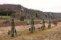
External tensioning works in Hausen im Tal station (2018)

Clamping room with internal clamping works, Bf Liebertwolkwitz, Stw Lt
.jpg)


In the case of rod lines, temperature-related changes in length must also be compensated for. Compensating levers of various types, which generally reverse the direction of movement, are used for this purpose.
At larger train stations, the signal boxes also had to interact with each other and, if available, with a command center . These dependencies can either be mechanical (see e.g. the Kerzers museum signal box ) or electrical, the latter variant being by far more common. For these electrical command and consent dependencies , which are collectively referred to as a station block, blocks are generally used in the German-speaking area and in Eastern European countries , which are connected via secure information transfer with the help of block fields .
The arrangement of the individual parts is different depending on the design.
- In the German standard signal box and many old types, the system consists of the lever bank with the adjacent block base in which the block locks are located and the route levers mounted above that on which the block box with the block fields stands and the lock box behind it .
- In the M43 design, developed from the unit design , components and dependency circuits of the S & H 1912 electromechanical interlocking are used for the station block. There is no longer a block attachment and thus block fields and inductors, but rotatable route levers with a magnet system. Because of the higher operating forces required, the handles are larger than in electromechanical interlockings.
- In the related station block 51 , this route lever box is also omitted, the route levers are free-standing and supplemented with signal lamps and buttons, the station block functions are implemented with relay circuits and Daisenhofer's locks in the lock box . When a route lever is moved into the end position, it is automatically set if the preconditions are met, and then, depending on the position, the approval or command is issued or the route definition and signal travel position takes place.
- With the Austrian standard design 5007, the valve body with the route toggles is located above the lever bank ; On the one hand there is the block apparatus with the block fields and on the other hand the track indicator . With the conversion of 5007s to light signals, either signal toggles were attached or the operation of the signals was integrated into a display panel .
- In British signal boxes, the locking register is located under the floor of the control room in most types.
All parts work together as a complex mechanical system. They make it possible to secure the route (see also the route ) for train journeys under the specifications of the signal dependency defined in the railway building and operating regulations .
Functionality and operation
Essentially, a route in the mechanical interlocking is set up and secured as follows:
- The signal box operator (signal box attendant or dispatcher) brings all equipment in the guideway and, insofar as they serve as flank protection, into the correct position in the neighboring tracks.
- Then he mechanically locks the switch, bolt, track lock and track lock signal lever by turning the route lever . He is also responsible for visually checking the route to make sure that the tracks being used are free of other vehicles or obstacles. By turning the route lever, the hand latch of the associated signal lever is released. The turning of this signal lever is still prevented by the route lock.
- Then he blocks the route definition field belonging to the station block . This affects the route locking lock in the block base. This block lock sets the traversed route lever in a block- electrical manner and releases the control lever for the main signal.
- As the last step, he throws the signal lever and brings the main signal into the driving position.
The thrown signal lever again mechanically locks the route lever, which is fixed electrically, so that the signal dependency is also implemented in interlockings without a station block; Step 3 is not applicable in this case.
After the train journey has taken place and the train has cleared a precisely defined point, the so-called train termination point, with a train termination signal , the block-electrical definition of the route is usually resolved manually when entering the train , and by the action of the train when leaving. The operator then returns the system to its basic position in the reverse order of operations.
All four steps for setting and securing the route for a train are also implemented in modern signal boxes. There, however, the individual steps run, at least partially, automatically.
Decisive for the location and the number of mechanical interlockings was not only the distance between the points, which depended on the greatest possible length of the wire pull cables, but primarily the overview of the actuation area including the possibility of a final train test . Since the trains do not run on sight because of their long braking distance , the attendant must check the clearness of the route by looking immediately before allowing the train journey , especially at night or in fog (see also route test ). At the same time, it was and is necessary to be able to reliably detect the end of the train at entrances, if possible without leaving the office. It follows that, even in smaller stations, it was not possible to get by with just one signal box ( central signal box ), but required two signal boxes, one at each end of the station ( end signal boxes ). One of them, the command signal box , was operated by the dispatcher, the other, the guard signal box , the switch attendant. Large train stations required several guards and possibly also dispatcher interlockings in order to be able to overlook the entire station area. Some railway administrations, for example the Royal Saxon State Railways , preferred instead to combine the posts of dispatcher and train supervisor . The dispatcher then had his place in the reception building and only served one command point without operating devices for external systems, while the guards at the terminal interlockings carried out the shunting operations independently and carried out train journeys on behalf of the dispatcher on behalf of the dispatcher.
development

Initially, the point keeper had to bring each point into the correct position using its setting device on site. There were not yet any technical constraints or dependencies that would help to set up and secure the route correctly. The switchman was solely responsible. The rapid expansion of the rail network and the associated increase in train and shunting operations required an improvement. Above all, equipment was needed to secure the switches before and during the train journey.
In the first step, switch locks were used that the switch attendant attached to the switches; later they were permanently and permanently installed. In the case of a security manual lock, the key can only be removed in the locked position, so a key in the hand of the guard gives security about the position of the locked device. Before a train ride, the switch attendant set the switches in the correct position, locked them with the switch lock and hung the keys on a key board where each key had its place. Only when the switch attendant had attached all the keys intended for the train journey to the key board was he allowed to give the train permission to travel. This was done initially with a hand signal with the help of a signal flag, later by setting a stationary signal to open.
The key board for temporarily attached hand locks has been retained to this day as a fallback level for malfunctions, even in modern interlockings.

When the previous process no longer met the increased need for security , mechanically operating key works were developed . To put it simply, there is a factory lock as a counterpart in the key system for every turnout lock that was installed outside, into which the same key fits. If a train ride is to take place, the switch attendant locks the keys of the locked switches in the corresponding factory locks of the key factory. If all the keys belonging to a route are in the key system, the main signal key in another factory lock can be unlocked. Unlocking this key locks the other keys in their locks. With the master signal key, the attendant then closes the lever lock of the signal lever, and in some cases the local control device for the signal, and sets it to drive.
The key work is regarded as the forerunner of the mechanical interlockings, because it was the first to implement signal dependency in a relatively simple way . Nevertheless, the procedure was still time-consuming because a lot of staff was still needed to operate the switches and signals on the spot.
In Germany, the first mechanical interlocking, from which points and signals could be remotely controlled and centrally secured, was put into operation by the English company Saxby & Farmer in Stettin in 1867. In the following decades, many German companies also developed and built mechanical interlockings in a whole range of different designs. These included signal boxes that used rods or compressed air lines for power transmission instead of wire pulls. But the latter could not prevail. The numerous, completely different interlocking designs already led to maintenance problems at the beginning of the 20th century. The Prussian State Railways in particular developed a new interlocking design based on the » Jüdel « design . In 1911 five prototype plants were built in the west of Berlin, after which the new "unit design" was declared binding for new plants throughout the Reich in 1915. Up until the twenties, signal boxes of the old types were completed in order to use up stored material. Since then, this "standard design" of the mechanical interlockings has only been changed in detail.
Designs
There are various types of mechanical interlockings. In some cases, the manufacturers only built the signal boxes of other manufacturers under license. The following manufacturers are or have been using designs in Germany:
- AEG
- Bruchsal
- Unit (built by several manufacturers)
- Esslingen
- Fiebrandt
- guest
- Harwig
- Hein & Lehmann
- Jewel
- Krauss
- Müller & May
- Nöll
- Scheidt & Bachmann , e.g. E.g .: signal box Tannenbergstrasse , Bergisch Gladbach
- Siemens & Halske
- Late
- Stamer
- Thomass
- Vögele
- Weinitschke
- Willmann
- Zimmermann & Buchloh
Deutsche Bahn puts the service life of mechanical interlockings, in which operation is worthwhile from a technical and economic point of view, at 80 years. In early 2006, the DB operated mechanical interlockings with 27,590 actuating units. The main designs are Einheit and Jüdel . According to the Deutsche Bahn, the operating and maintenance costs of mechanical interlockings are up to nine times higher than those of modern technology. The oldest signal box in the DB area was built in 1887 (as of 2006).
In Austria, the following manufacturers are or have been using designs:
- Siemens and Halske (including the Austrian "5007" control interlocking)
- Südbahnwerke
- Götz and sons
- Signal boxes of the German standard design from different manufacturers
Austrian signal box designs are still in use today on railways of old Austrian origin, u. a. in the Czech Republic , Slovakia , Hungary and Slovenia .
Mechanical interlockings from the following manufacturers were in use in Switzerland:
- Schnabel & Henning, Bruchsal machine works
- Max Jüdel
- Hasler
- Vögele
- Toilets
- The PLM built as operator of the route (Lyon-) La Plaine-Genève and the Chemin de fer de l'Etat de Genève , the signal boxes to French principles.
Building shapes
The simplest form is the installation of the interlocking equipment in the mostly already existing service building of a train station. This meant that the operation, if it was compatible with the workload, could be taken over by existing staff (so-called "combined service"). In simple conditions, the lever mechanism was also set up in front of the building in the open, later these systems were often provided with weather protection. The typical, glazed signal box extensions were built around the 1920s. Because the train length increased over time and the usable track lengths had to be adapted, whereby the line lengths exceeded the controllable level, another signal box had to be built at the distant station head, usually in the form of a dependent attendant signal box. This form with the command signal box in the station building at platform level and a tall guard signal box at the other head of the station can still be found at many stations. The division of signal boxes according to the shape of the building, which is often used by outsiders, has little to do with the function and technology of the signal box, especially since this distinction is only used for old systems with mechanical or electromechanical control technology, which provide an overview of the railway systems supervised by the signal box for the purpose of checking clearance Inspection "require. Here in particular
- Signal towers that were erected on the side of a railway system and have an elevated operating room above the tensioning systems,
- Bridge signal boxes that have their control room in a bridge across the supervised railway systems and
- Equestrian interlockings, the control room of which is raised in the longitudinal direction above the railway systems, specially named.
What they have in common is that they are located in train stations in which a suitable place between the tracks with an overview of the systems for the purpose of vacancy reporting could not otherwise be set up.Typically, in these buildings, tensioning systems cannot be accommodated in the building and are therefore on the edge of the track system.
Examples of mechanical interlockings still in operation
The mechanical interlockings are quickly being replaced by more modern ones , for example by electronic interlockings . The table shows a small selection of the mechanical interlockings still in operation in 2020.
| railway station | country | Design | comment | image |
|---|---|---|---|---|
| Bad Aussee | Austria | 5007 | In operation | |
| Biel RB | Switzerland | Jüdel, Bruchsal J | In operation, to be replaced by ESTW in 2021 | |
| Fridingen station | Germany | Standard design | In operation |
|
| Hausen im Tal station | Germany | Standard design | In operation |
|
| Ketton | Great Britain | Midland tap lever frame | In operation | |
| Mattighofen | Austria | 5007 | In operation | |
| Quantities station | Germany | German standard design | In operation |
|
| Munderfing | Austria | 5007 | In operation | |
| St. Martin am Grimming | Austria | German standard design | In operation | |
| Nieukerk | Germany | Standard design | In operation, pilot site for technical monitoring of the track | |
| Utting | Germany | Standard design | In operation, pilot site for technical monitoring of the track |
See also
Web links
Individual evidence
- ↑ Performance and financing agreement: Infrastructure status and development report 2016. Deutsche Bahn AG, accessed on September 5, 2018 .
- ↑ Jörg Bormet: Requirements of the operator on the life cycle in route safety technology . In: signal + wire . tape 99 , no. 1 + 2 , 2007, ISSN 0037-4997 , p. 6-16 .
- ↑ Deutsche Bahn AG, DB Systemtechnik: Activity Report 2006 ( Memento of July 18, 2011 in the Internet Archive ) (PDF, 1.6 MB), p. 32.
- ↑ a b Hans G.Wägli: levers, bolts and signals . Diplory Verlag, Grafenried 2018, ISBN 978-3-03306410-2 .
- ↑ a b List of German signal boxes. Retrieved May 5, 2020 .