Humidification distance
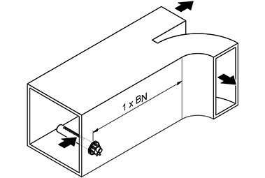
In air conditioning technology, the humidification section B N is understood to be the section within a steam distribution system that the water vapor emerging from the steam distribution pipe requires in order to be absorbed by the air flowing past to such an extent that it is no longer visible as fog . In addition to the humidification section, an expansion and mixing zone should also be provided in order to ensure the hygienic and complete absorption of the steam from the air.
definition
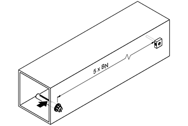
The humidification section consists of the mist zone and the subsequent expansion and mixing zone. The path behind the air humidification system is referred to as the fog zone - from the introduction to the complete absorption of the amount of steam by the system air. This is followed by the expansion and mixing zone. In this section of the route, the moisture introduced mixes evenly with the air flow. The length of the required humidification distance depends on the component following in the air direction. Correct dimensioning of the humidification distance is extremely important to avoid condensation phenomena within the air ducts. Knowing them is also of fundamental importance for correct humidity control, since the control sensors should only be placed where balanced humidity values are available.
The determination of the humidification distance «B N » depends on various factors. The humidification distance table can be used to easily determine the humidification distance «B N ». The guide values given in the table refer to a supply air temperature range of 15 ° C to 30 ° C.
Humidification distance table for a simple steam distributor
| Inlet humidity φ1 in% RH | Length of the humidification path B N in m
Exit humidity φ2 in% RH |
|||||
|---|---|---|---|---|---|---|
| 40 | 50 | 60 | 70 | 80 | 90 | |
| 5 | 0.9 | 1.1 | 1.4 | 1.8 | 2.3 | 3.5 |
| 10 | 0.8 | 1.0 | 1.3 | 1.7 | 2.2 | 3.4 |
| 20th | 0.7 | 0.9 | 1.2 | 1.5 | 2.1 | 3.2 |
| 30th | 0.5 | 0.8 | 1.0 | 1.4 | 1.9 | 2.9 |
| 40 | - | 0.5 | 0.8 | 1.2 | 1.7 | 2.7 |
| 50 | - | - | 0.5 | 1.0 | 1.5 | 2.4 |
| 60 | - | - | - | 0.7 | 1.2 | 2.1 |
| 70 | - | - | - | - | 0.8 | 1.7 |
| φ1 in% RH: Relative supply air humidity before humidification at the lowest supply air temperature
φ2 in% RH: Relative supply air humidity after the steam distribution pipe at maximum output |
||||||
|
Calculation example
given: φ1 = 30% RH, φ2 = 70% RH Humidification distance B N : 1.4 m |
Influence of humidification on the control quality
The humidification distance is of particular importance in steam humidification. The water vapor emerging from the steam distribution pipes initially condenses in the air flow and is visible as a mist within a certain distance (humidification distance). This is followed by the expansion and mixing zone, in which the system air is evenly mixed with the amount of steam introduced. This circumstance must be taken into account solely with regard to a hygienic mode of operation when dimensioning the humidifying sections. For optimal control results, optimal moisture distribution at the installation location of the measuring sensor is essential. The humidification distance depends on various factors and forms the basis for determining the required minimum distances to the following system parts and measuring sensors.
How can you shorten a humidification distance?
To a certain extent, condensation is promoted by the contact of the water vapor with the cooler system air. The main reason for condensation, however, is the unfavorable distribution of the amount of steam over the channel cross-section along a steam distribution pipe. The required humidification sections are not available, especially when retrofitting. In such cases, the use of multiple steam distribution systems is often successful. This enables the water vapor to be distributed as homogeneously as possible over the entire air flow with correspondingly short humidification distances. The homogeneity index is a valuable yardstick for evaluating steam distribution.
Humidification distance table for multiple steam distributors
| Inlet humidity φ1 in% RH | Length of the humidification path B N in m
Exit humidity φ2 in% RH |
|||||
|---|---|---|---|---|---|---|
| 40 | 50 | 60 | 70 | 80 | 90 | |
| 5 | 0.22 | 0.28 | 0.36 | 0.48 | 0.66 | 1.08 |
| 10 | 0.20 | 0.26 | 0.34 | 0.45 | 0.64 | 1.04 |
| 20th | 0.16 | 0.22 | 0.30 | 0.41 | 0.58 | 0.96 |
| 30th | 0.10 | 0.17 | 0.25 | 0.36 | 0.52 | 0.88 |
| 40 | - | 0.11 | 0.20 | 0.30 | 0.45 | 0.79 |
| 50 | - | - | 0.13 | 0.24 | 0.38 | 0.69 |
| 60 | - | - | - | 0.16 | 0.30 | 0.58 |
| 70 | - | - | - | - | 0.20 | 0.45 |
| φ1 in% RH: Relative supply air humidity before humidification at the lowest supply air temperature
φ2 in% RH: Relative supply air humidity after the steam distribution pipe at maximum output For duct widths <600 mm, the humidification distance for multiple steam distribution systems is extended by approx. 50% |
||||||
|
Calculation example
given: φ1 = 30% RH, φ2 = 70% RH Humidification distance B N : 0.36 m (for multiple steam distribution systems) |
Minimum distances to be observed for the expansion zone
So that the water vapor emerging from the steam distribution pipe does not condense on the downstream system components, downstream system components must have a certain minimum distance (based on the humidification distance «B N ») to the steam distributor.
literature
- Air humidification. 4th edition. Oldenbourg Verlag, author: Erich Henne, ISBN 3-486-26289-0
- Recknagel pocket book for heating + air conditioning technology 72nd edition, Oldenbourg Industrieverlag Munich, editor Prof. Dr. -Ing. Ernst-Rudolf Scharmek, University of Dortmund ISBN 3-486-26534-2
- Planning criteria for air humidification, HYGIENE, author: Christian Bremer ISBN 978-3-9817618-0-1
- Planning criteria for air humidification, REGULATION, Author: Christian Bremer ISBN 978-3-9817618-1-8


