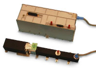
Electronic power conditioner
An Electronic Power Conditioner (EPC) is used to supply a traveling wave tube with the required operating voltages and together with it forms a traveling wave tube amplifier. If the associated preamplifier is also integrated into the EPC, it is called a Microwave Power Module (MPM).
function
The general function of an EPC can be represented as follows: The power supply (EPC) has the task of operating a traveling wave tube (TWT) and a preamplifier safely under all operating conditions and protecting both devices in the event of a fault. The EPC thus has to take on various functions, whereby a distinction must be made between primary and secondary functions.
Primary functions:
- Highly efficient generation of the high voltages required to operate the traveling wave tube from the variable, potential-free and significantly lower input voltage.
Secondary functions:
- Generation of telemetry signals and adaptation to the satellite system
- Control of the internal processes required for switching on a traveling wave tube
- Setting of the tube parameters necessary for the corresponding output
- Protective circuits to protect the traveling wave tube from improper operation or high voltage flashovers
- Adaptation of the telecommand interface to the satellite system
- Generation of auxiliary voltages for the channel amplifier with linearizer.
Block diagram
The block diagram of the analog and partially digital solution used so far is shown in the following block diagram.
functionality
The potential-free input voltage (VMB) is fed to a pre-regulator , which converts the input voltage into a constant output voltage (VB). This pre-regulator is one of the key components of the EPC, which influences various main parameters of the EPC and the traveling wave tube. The main features of the controller are high efficiency, high immunity to conducted interference , high controller stability and insensitivity to pulsed loads. All of these properties are best met by a buck regulator , a switch mode power supply (SMPS).
To suppress input voltage ripple and switching regulator malfunctions of the EPC, an input filter is inserted between the circuit breaker of the pre-regulator and the EPC power input .
A start-up series controller generates the voltage for the internal electronics. It switches off automatically as soon as the auxiliary voltage converter works.
The constant output voltage (VB) is fed directly to the heating converter and generates a square wave voltage for the traveling wave tube heating. No further voltage regulation is required, but the heating converter requires a start-up circuit to avoid inrush current peaks when the tube heater is cold.
The supply voltages for the channel amplifier are generated by an auxiliary voltage converter with internal overload protection.
The main converter is also supplied by this constant voltage (VB) and generates a square-wave output voltage through its push-pull stage. The main features of the push-pull converter are its high performance, optimized and low-loss oscillation behavior of the HV transformer, avoidance of overlapping switching of the switching transistors through a defined gap time and a gentle oscillation of the high-voltage diodes.
An important part of the power path is high voltage generation .
The type of high voltage generation and its continuation to the traveling wave tube have a lasting effect on the traveling wave tube behavior. With the output filter design, the tube can be switched on simultaneously with all high voltages without current peaks occurring in the helical current of the traveling wave tube. Through a serial high voltage concept, i. That is, generation of all high voltages with only one high voltage transformer and series-connected doubler stages for collector, helix and anode voltages, the high demands on the EPC can be achieved most efficiently. The stability of the collector voltages is only determined by the pre-regulator output voltage (VB). In addition, the helix and anode voltage are stabilized by series regulators in order to ensure constant high-frequency behavior of the traveling wave tube. The helix regulator is at housing potential and the cathode current regulator is at anode potential.
All internal processes of EPC are controlled by the digital control unit . This function block is usually integrated in an application-specific integrated circuit (ASIC) and has the following tasks:
- Generation of the clock frequency
- Generation of the control signals for the heating, main and auxiliary voltage converters
- Control of the switch-on sequence of the high voltages
- Processing of the telecommand signals
- Generation of the telemetry status signal
- Protection of the EPC against malfunctions including an automatic restart unit (ARU).
Areas of application
The "heart" for communication satellites are power amplifiers. They are used to transmit the data generated there either to earth or to other communication satellites. Today produces u. a. the company TESAT-Spacecom such EPCs and integrates them with traveling wave tubes from Thales Air Systems and Electron Devices to form traveling wave tube amplifiers.

