
Billing meter

The charge counter (also charge unit counter ) was used in electromechanically constructed local exchanges to record and record the connection charges and, as a result, to generate the telecommunications bill.
Manual placement
In the early days of telephony , there was only manual switching by the " Miss from Office ". Counting was not necessary with the earlier flat rates . However, it was soon recognized that this tariff was being overused by some participants . The introduction of new tariffs followed. For each connection established, the officer issued an interview slip, which served as the basis for invoicing.
Self-dialing operation

These small charge meters were used to count calls in networks with self-dialing. Each subscriber was assigned a separate charge counter in the exchange. They were housed in the local exchange in the frame for the selection, or in separate rooms for easier reading using analog photography.
In the case of a local call, regardless of the length of time when the calling subscriber hung up, a charge unit was counted at the end of the call. Long distance calls were counted by time and distance. The units were saved in a time zone counter (ZZZ) and at the end of the conversation transferred to the charge counter as a multiple count. The memory capacity of the rotary selector in the ZZZ was limited. The call was then automatically disconnected after 6 or 12 minutes and counting was initiated.
A transmission of the counting impulses in the form of charge impulses during the call was not yet possible because of the background noise. The transmission took place at the end of the conversation via the b-core. In the next stage of development, the transmission of the counting impulses during the conversation was developed without interfering noises. The transmission also took place via the b-wire with flattened pulses. The counter relay was switched on to the b-wire in the first group selector for a long-distance call. In the case of a long-distance call, the first charge pulse was transmitted when the called subscriber picked up the receiver and then, depending on the tariff, additional pulses were transmitted to the charge meter.
The counters at the participant were referred to in Germany in official German as fee displays.
construction

The fee meter essentially consists of
- Electromagnet
- Armature with pawl and return spring
- Counter
Similar to a DC relay, the electromagnet actuates the armature when current flows. The armature advances the counter by one step with every pull via a push latch. The counter contains four number drums. Often the four positions were no longer sufficient due to frequent speakers and expensive international tariffs. Charge meters with five or six digit drums were then used. The armature movement is transmitted to a drive wheel, which is firmly connected to the single drum, with each pulse. The rest works like the mechanical counter. In the event of an overflow, the counter starts counting again from 0.
System 50

In system 50, the following requirements were made for the charge meter:
- The armature must remain in the rest position with a current of 38 mA and be fully tightened with 46 mA.
- In the event of an excitation lasting 250 ms with 115 to 125 mA and a residual current of 16 mA, the armature must safely fall off again.
- With a subsequent excitation with 38 mA, the fault current test value, it must not leave its rest position.
The maximum value of the fault current and the minimum value of the response current differ by only 8 mA. This shows the severity of the test conditions for a meter. While there are no special time requirements for single counting in local traffic, certain requirements must be placed on the switching times when used in circuits with multiple counting. With a minimum duration of the counting current surge of 50 ms and a minimum pause of 100 ms, the counting speed is 6.6 steps per second. The meters must still work properly under these conditions. At least four million increments are required for the service life of a billing meter without any signs of wear and tear.
Reading of the charge counter
In the early days, the charge meters were read by hand and entered in a list. This was followed by the development of a tube with a built-in camera and built-in lighting for reading a 100 field.
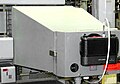
Meter reading Tubus, Germany East

Meter reading photography system 40

Meter reading of a 100 field, Germany East

Fee reading of a 100 field, Switzerland

Tube with camera, Switzerland

Photographic documentation of the counts, exhibit in the Technical Collections Dresden


Austria

The counting takes place in the Dietl dialing system using a loop counter that counts the occupancies after a certain time, regardless of whether a connection has been established or not. From 1930 the loop counter was read with the counter reading photography.
With regard to the different colors on the Austrian call counters, the following background information is important:
In the beginning, a tariff pulse was given every 36 seconds in local traffic (at that time at 0.12 ATS or twelve groschen), 100 pulses resulted in 3600 seconds with active occupancy, which corresponded to one hour of charging.

Until about 1990 only WHOLE hours were billed, the "decimal places" were not taken into account. To make things easier for the readers, the full hours were in one color (white on black) and the parts of the hours in the other color (black on white).
The meter readings were photographed. The editors got the films to read and capture. The values were read from the film negatives; the entire hours were shown in black and white. For a while there were so-called cover panels for connections that were not wired but provided with counters, which you put on the relevant counters in order not to have to record the count.
According to a later service instruction, however, unconnected participant sets also had to be equipped with meters, so that the number of cover panels available at the time was no longer sufficient.
At that time, red but transparent cellophane ribbons were introduced, which were stuck over the unused counters. If the relevant counter field was now photographed, the counter readings were not visible on the negative, but the electoral room staff could still read the counter readings through the cellophane.
Every second month, the counter fields for 100 participants at the I.VW were photographed. The films were first sent to the telephone billing department (TRA), where they were read by officers using a viewing device and used to issue telephone bills.
There was an own meter reading photographer. Intermediate readings were made conventionally by reading the voting room attendant.
Web links
- Transmission of the counting impulses during the conversation, circuit diagram with animation
- Transmission of the counting impulses to the charge display circuit diagram with description
- Mechanical charge meters in the exchange
Individual evidence
- ↑ Handbook of Telecommunications Technology, Basic Series, Volume 8, Basics of Switching Technology, Deutsche Postgewerkschaft, 6th edition 1980, p. 41
- ↑ Handbook for Telecommunications Craftsmen, Volume 5, Vermittlungstechnik, Deutsche Postgewerkschaft, 1st edition, 1981, p. 32
- ↑ learning leaves switches, basic knowledge of the structure and operation of a OVStW, German Federal Post Office, 8/1971, p 37