Connector (UML)
A connector (Engl. Connector ) is a model element in the Unified Modeling Language (UML), a modeling language for software and other systems.
A connector models a connection between two or more connectable elements , i.e. parts , ports , parameters and variables . Please note that the model elements class , interface or component do not appear in this list . This is the main difference between associations and connectors. Connectors specify connections between parts of a classifier , while associations describe connections between the classifiers themselves.
Meaningfulness of connectors compared to associations
The need for the connector model element arises primarily from the weak point that modeling with classes and associations is often insufficient to represent the internal structure of a system.

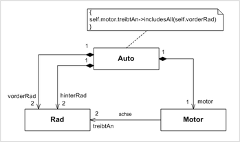
For example , the figure on the left shows a class diagram that is supposed to model the internal structure of a car. The fact that a car has two front wheels and two rear wheels is shown with two compositional relationships between Autoand Rad. Another compositional relationship shows that every car contains an engine. With the help of an association it is relatively easy to show that a motor drives two wheels. Without additional restrictions on the class Auto, however, some degenerate configurations of characteristics would be conceivable according to this class diagram. For example, a motor could drive a rear wheel and a front wheel. The engine of one car could also be connected to two rear wheels of another car. Only the restriction Autoassociated with the class excludes these cases.
The same internal structure of a car can be represented using a composition structure diagram. The degenerate cases described above cannot occur here. A connector between the parts :Motor and vorderRadis sufficient to fully specify the structural restrictions; no additional restriction is necessary.
Composition and delegation connector
UML2 distinguishes between two special types of connector: the composition connector and the delegation connector.

A composition connector connects two ports of two components that work together, that is , are composed into a larger unit . The port of one component must offer an interface that the port of the other component requires. The composition connector is not shown graphically as a continuous line between the two ports involved, but as two interlocking symbols for an offered and a required interface. In the figure on the left there are two composition connectors. One connects EmailManagementwith MailEingang, the other EmailManagementwith MailAusgang.

A delegation connector connects a port of a classifier with a part inside the classifier. It stands for the fact that messages that arrive at the port from outside are forwarded to the connected part, ie they are delegated . Two delegation connectors are shown in the illustration on the left. One connects the Management Portwith the part :Benutzerverwaltung, the other an anonymous port, on which e-mails arrive, with the part :Meldungsdatenbank.
Differences to UML 1.4
The connector model element was newly introduced in UML2.
literature
- Christoph Kecher: UML 2.0 - The comprehensive manual. Galileo Computing, 2005, ISBN 3-89842-573-8
- Conrad Bock: UML 2 Composition Model . in Journal of Object Technology, vol. 3, no.10, November-December 2004, pp. 47–73, ( online )
