Ossanna circle
The Ossanna circle is the representation of the current locus of a three-phase asynchronous machine in the complex plane . It enables a relatively simple representation of the power, torque and loss of an asynchronous machine in generator and motor mode depending on the slip. The Ossanna circle only ever applies to the operation of a machine with one voltage, usually the nominal voltage. If the voltage changes, the diameter of the circle changes.
If the stator resistance is neglected, the result is a simplified form, the Heyland circle. This applies as a first approximation and is characterized by the fact that the torque line coincides with the imaginary axis.
This circle diagram of the asynchronous machine was published by Alexander Heyland in 1894 and presented in a further developed form by Johann Ossanna in 1899 .
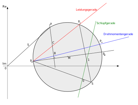
The following names correspond to those in the picture "Ossanna Circle".
Reading the characteristic values
P 0 denotes the idle point, P 1 the real short-circuit point and P ∞ the ideal short-circuit point (rotor resistance = 0). The diameter is the distance between P 0 and P Φ . The power line is the distance between P 0 and P 1 . The torque line between P 0 and P ∞ .
Each state of the machine is a point on the Ossanna circle. If one selects such a point P and the perpendicular falls on the diameter, the effective power, the torque and the power loss can be determined immediately. Points B and C are the points of intersection with the torque line and the power line. The mechanical active power P m corresponds to the scaled distance between points P and C. The distance between P and B corresponds to the torque. The distance between B and C describes the losses occurring in the rotor winding.
Construction of the circle
If the complex flows of three working points of the machine are known, the circle can be determined geometrically from these.
The slip for each point can be determined using a slip line. This is constructed by drawing a connection to P ∞ from any point S on the circle . Any straight line parallel to this connection can be used as a slip line. The axis scaling results from point "0" (intersection of the line between P 0 and S with the slip line) and point "1" (intersection of the line between P 1 and S with the slip line). Otherwise the slip line is characterized by a linear scale. In order to determine the slip from any point P, a straight line must be drawn between P and S, the intersection of which with the slip line on your scale gives the slip.
literature
Eckhard Spring: Electrical machines, Springer textbook, 2006 ( ISBN 9783540282419 )
