Final line procedure
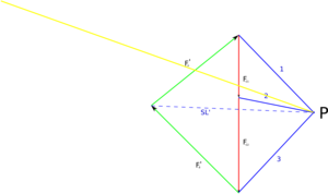
The final line method is a drawing method to determine forces that act on an object. First you draw a true-to-scale force plan and a site plan with all known directions of the forces. All known forces are hung one behind the other. Since we cannot break the basic laws of physics, all forces have to cancel each other, so all arrows point in a circle and complement each other with the unknown forces to form a polygon (starting point = end point). This is a basic requirement for statics. In statics, nothing usually moves, so no force may “remain” in the force plan, but all forces must cancel each other out. In the next step you choose any pole point P inside or outside the force plan and connect all points at which forces meet with this point. The first line is shifted parallel to the site plan and brought to the intersection there with the respective line of force . Line two then intersects that point and so on. At the end you get the unknown so-called final line. These are shifted back into the force plan in parallel and can thus determine the missing forces.
Example: hydraulic lever

|
The following initial situation: A hydraulic lever is freely supported in bearing A (direction and magnitude of the force are unknown). The arm is loaded by its own weight ( ) and its load ( ). The hydraulic cylinder acts in B (the direction of its force ( ) is therefore fixed).
In the following steps we will use simplified sketches. = 8 kN = 12 kN = unknown = unknown |
| We now draw a true-to-scale site plan and a force plan. F A is not known in terms of direction or size, so it is only drawn as a circle on the site plan. All other directions of the forces are known. We can enter F G1 , F G2 and F B. (Important !: do not draw any arrows, it is all about the line of action )
|

|

|
Now we go to the plan of forces and draw a point. The so-called pole point P. We connect this point to every point in the force plan where two forces meet. Where exactly this point is is relatively irrelevant, but there are ways to set it very cleverly, but more on that later. Here we put it decentrally. The individual lines, called pole rays, are numbered in the order of the cut. |
We continue by shifting pole beam 1 in parallel until it passes through point A. Why through A? Very easily! This "intersection point"  tells us that the pole beam in the site plan must cut through the effective directions of the forces F A and F G1 . Since we do not know any direction from F A , we have to accept the point because it is certainly on it. tells us that the pole beam in the site plan must cut through the effective directions of the forces F A and F G1 . Since we do not know any direction from F A , we have to accept the point because it is certainly on it. So we move pole ray 1 in the direction of point A. The length of the ray does not matter, only its direction is important, but it should be chosen so that the force to be cut is actually cut. For the sake of clarity, we write the number of the pole ray at both ends. We mark the intersection with F G1 (here orange). Tip: parallel shifting works best with 2 set squares. With one of them you set the direction. With the second you fix the first and can then move it. |

|

|
Now the next step follows: We shift pole ray number 2. Until it goes through the intersection of pole ray 1 with F G1 . Then mark the point of intersection between pole beam 2 and F G2 again . Why F G2 ? Because pole beam 2 "connects" F G1 with F G2 in the force plan . A triangle in the force plan creates an intersection point in the site plan. |
| Hokage third with Polstrahl number Play as long as the Second move until he crosses the intersection of point 2 and F G2 goes, and in this case the intersection with F B draw. |

|

|
Now it would normally be the next pole beam, but we don't have any more. But we have the provisional final line SL '. We can't really do anything with it except to improve it. The last real final line here goes through the point A and the intersection of Polstrahl 3 F B . So let's just connect the two dots. In the final line, the length does not matter, only the direction. |
| We now move the final line SL into the force plan until it passes through the pole point P. |

|

|
Simply extend the force F B in the force plan until it intersects the end line. This then results in the only possible direction and size for F A since all forces in the statics basically cancel each other out.
Now measure with the ruler how long F A and F B are, convert with the ruler and we have graphically determined 2 missing forces. |


