Environment diagram (computer science)
Environment diagrams (engl. Environment diagrams ) for the graphical illustration of the environment models of functional programming languages such as LISP or Scheme . They are especially used didactically to illustrate the differences between static and dynamic binding . Environment diagrams are based on the book chapter The Environment Model of Evaluation .
Environment model
The structure of a program can be broken down into individual environments ( ).
- env 0 represents the initial environment. It represents the basic functionality (arithmetic functions and other operators, e.g. +, -, =) of a language. env 0 is always present and is implicitly assumed ("User Global Environment") . All other environments rely directly or indirectly on env 0 .
- env 1 is the main or framework program (“User Initial Environment”). env 1 contains function and variable declarations. A "higher" environment env 2 is only created when a function is called or with let or let * .
- env 2 ... env k are equivalent to env1. An env 2 environment can itself declare its own functions (methods) or variables (attributes). Here, too, a function call leads to an increment of the environment level.
- Environments can be nested (with Scheme using lambda, let and define).
Example (Scheme)
   (define a 1)  ;env_1: a->1
   (define (f x) (* x a))  ;env_1: f->(* x a), a->1, x->5
   (f 5)  ;Funktionsaufruf: neue Umgebung env_2 wird erstellt
Elements of environment diagrams
The following elements appear in the environment diagram:
Rectangles
Rectangles represent an environment that contains binding pairs.
Dashed rectangles
Dashed rectangles represent a function body. In the upper part of such a rectangle, the parameters of a function are written in brackets. The actual function term then follows in the lower part. Function terms can themselves call other functions or contain let and let * expressions, creating a new environment.
Circle pairs
Circle pairs stand for functional objects . One of the circles of the circle pairs refers to the function body of the function object. The second circle points to the definition environment, i.e. to the environment in which the function was defined (usually one environment level lower).
Arrows or edges
Directed edges refer from the function object to the definition environment and to the function body.
Example of an environment diagram
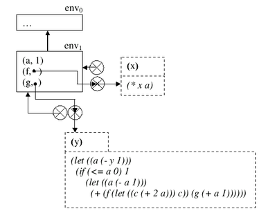
The above code example would look like this in an environment diagram:
Continuation of the example
Building on the last example, here is an extension and completion in Scheme code:
   (define a 1)  ;env1: a->1
   (define (f x) (* x a))  ;env1: f->(* x a), a->1, x->5
   ((lambda (a) (if (<= a 0)
                    1
                    ((lambda (a) (+ (f ((lambda (c) c) (+ 2 a))) (g (+ a 1))))
                     (- a 1))))
    (- y 1))
Environment diagram:
Recipe for creating an environment diagram
(Environment diagrams for dummies)
- You don't need to make a rectangle for the area , so you write down "env0" first.
- Note the outermost functions and bindings in the first neighborhood env_0.
- New environments are created by the following constructs:
- let and let *
- define
- ...
- It should be noted that a new environment is created for each procedure evaluation.
- New environments are created by the following constructs:
- Functions are linked to the old environment by means of 2 circles as function objects with the help of 3 arrows. The first arrow points from the parameter of the function (which is represented by a gap) to the edge of the left circle. The second arrow points from the center of the left circle to the edge of the functional environment (which is not numbered with env_N). The third arrow leads from the center of the right circle to the edge of the area in which the function was defined.
literature
- Klaus Hinrichs: Computer Science 1 lecture script for Scheme programming (PDF; 733 kB) University of Münster
Individual evidence
- ^ The Environment Model of Evaluation . ( Memento of the original from January 18, 2006 in the Internet Archive ) Info: The archive link was inserted automatically and has not yet been checked. Please check the original and archive link according to the instructions and then remove this notice. In: Abelson and Sussman: Structure and Interpretation of Computer Programs .


