Curtain antenna


A curtain antenna is a directional antenna , which usually for broadcasters to short wave , for example, in the short-wave transmitter Wertachtal was used.
conditions
One goal of shortwave broadcasting is to securely supply a geographic destination with information. To do this, you need enough power at the transmission location and the right frequency to match the radio weather . In order to meet these conditions as economically as possible, curtain antennas have been developed that meet these requirements: high yield of the existing transmitter power (gain) and usability with several frequencies in order to save installation space and reduce the number of antennas required.
construction
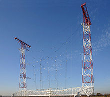
A curtain antenna consists of a combination of several antennas which are arranged in front of a reflector wall. The antennas and reflectors are suspended with steel cables and insulators like a curtain between two, usually free-standing, support masts.
Profit
The simplest form of antenna is the dipole . It can be easily made from wire. This also makes it inexpensive. If you combine two dipoles horizontally into one line, you get a bundling of the radiation direction horizontally by half, the resulting gain is 3 dB . If you combine 4 dipoles in one line, the gain increases to 6 dB with a further halving of the horizontal radiation width. This procedure quadruples the radiated power in the desired direction through antenna gain. If you double this dipole line vertically (= "stagnate"), the vertical diagram of the antenna changes in the same way. The antenna gain increases to 12 dB. By adding a further 8 dipoles in vertical stacking (now a field of 4 x 4 dipoles), the gain arithmetically increases to 24 dB. This value is the theoretical value. Losses occur through balancing and distribution. For a curtain antenna with 16 elements, a gain of 20 dB can be expected in practice. This means a hundred times the radiation power compared to the transmitter power: 500 kW become 50,000 kW radiation power ( ERP ) in the desired direction.
Broadband design
If the "simple wire" in the dipoles is replaced by a trap-shaped arrangement of wires, the usable frequency range of the antenna is expanded without loss of gain and directivity : it becomes broadband. In addition to its design frequency, it can also be operated on 3 to 4 neighboring radio bands with an appropriate tuning device. This saves space and costs during construction, because one antenna structure can be used for several frequency bands.
Extended design
The areas between two masts are often used twice. They are then called double wall antennas. In the center between the masts there is a cable network (reflector network) which divides the room into two antenna areas: "In front of the curtain" and "Behind the curtain". There is at least one antenna on each side.
An example
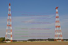
The picture shows a triple use of an antenna field at the former broadcast station Wertachtal in Bavaria. This version had additional special features.
On the 210 ° side (in the picture facing side, marked in red) there is an antenna with 4 rows of 4 elements for 6 and 7 MHz. On the opposite side (30 °) 16 elements for 11, 15 and 17 MHz are mounted on the left (in green). On the right side there is another antenna with 20 elements (purple) for 7 and 9 MHz, of which the bottom row with 4 dipoles could be used as an antenna for the close range at 9 and 11 MHz. In practical operation, a curtain antenna could be used on both sides independently of the other side, at frequencies with sufficient distance.
New approaches
Since 1993 there has been a new design of the curtain antenna, developed in cooperation between Thomson CSF (later Thales ) and TéléDiffusion de France (TDF) for use as a replacement for the old shortwave transmitters in Issoudun and Allouis. Here the entire antenna construction is self-supporting, fully rotatable and firmly connected to a transmitter. The so-called ALLISS antenna was created .
nomenclature
The CCIR (today ITU ) has standardized the designation of curtain antennas.
The designations follow this scheme: HR (S) followed by 3 numerical values m / n / h, where h can be a decimal fraction.
- HR = curtain array with H orizontalen dipoles and R eflektorvorhang
- If available: S = antenna can be swiveled electrically or rotated mechanically ( S lewable)
- m: Number of emitters (half-wave dipoles) in each line
- n: Number of emitters (lines) one above the other
- h: Height of the bottom row of the radiators above ground, possibly in fractions of the wavelength
An antenna with two rows of 4 dipoles with a wavelength above ground is an 'HR 4/2/1'. The antenna from Hörby in the picture above was at least an HR 4/4 / 0.5. It is not possible to tell whether it was electronically pivotable by means of a phase change (see phased array antenna ) - in that case, or if it had been rotatable as a whole, it would have been an HRS 4/4 / 0.5.
literature
- Rothammels Antennenbuch , 12th edition, page 829.
- Otto Zinke, Heinrich Brunswig: Textbook of high frequency technology . 1st edition. Springer-Verlag, Berlin - Göttingen 1965, ISBN 978-3-662-00477-7 , pp. 224-228 .
Web links
- Walter Brummer: Pictures from the transmitter Wertachtal, Bavaria. In: www.wabweb.net. November 30, 2014, accessed May 2, 2019 .
Individual evidence
- ↑ ITU: Transmitting antennas broadcasting in HF. In: RECOMMENDATION ITU-R BS.80-3. June 1990, accessed on July 22, 2019 .
- ↑ TCI International, Inc .: Data sheet curtain antenna HR 4/4 for shortwave broadcasting. In: Shortwave Broadcast Antenna Model 611. 2011, accessed on July 22, 2019 .
- ↑ Telefunken, Department of High Frequency Technology, Ulm: Broadband curtain antennas for shortwave transmitters. July 1976, Retrieved May 2, 2019 .
- ↑ Telefunken Sendertechnik GmbH: Patent for broadband HF curtain antennas. December 10, 1996, accessed May 2, 2019 .
- ↑ CCIR: Recommendation 705: HF transmitting antennas, characteristics and diagrams. In: ITU Library & Archives collections. 1990, accessed November 21, 2019 .

