
Harvester
A combine harvester (see also in English. Combine harvester ) is an agricultural harvesting machine for mowing , threshing of grain - or seeds, the separation of straw and cereals and seeds , the cleaning of grains and seeds from the chaff and the filing of the Straw in swaths for later salvage as litter or flat distribution of the chopped straw for natural fertilization on the field.

| 1) reel 2) cutter bar 3 ) intake auger 4) inclined conveyor 5) stone trap 6) threshing drum 7) concave | 8) Tray shaker 9) Stepped floor 10 ) Fan 11 ) Upper sieve 12 ) Lower sieve 13) Returns auger 14) Returns | 15) Grain auger 16) Grain tank 17) Straw chopper 18) Driver's cab 19) Motor 20) Unloading auger 21) Turning drum |
Description of the assemblies
Header
The front header is on the combine. Different units are used depending on the type of threshed crops . If the header is wider than three meters (working widths of almost 14 meters for grain and 12 meters for maize are possible), the header must either be dismantled or (hydraulically) folded up for road travel. The cutting unit is then transported with a cutting unit carriage.

Dismantled cutting unit on trolley. Stalk dividers folded down on the sides. On the cutter bar are Grainlifter mounted (here: red or metallic triangular angle) for erecting stored grain .

Folding cutting unit (special design) saves dismantling and loading onto transport trolleys.
View of the cutting unit while working

Cutter bar (without crop lifter), reel (above, red) and cross auger (middle). To the left of the center of the picture, conveyor fingers protrude from the cross auger. respectively.

Rapeseed header

Corn header

Corn header
Pickup attachment
Combine harvester with grain harvesting header


.jpg)


Cutting units
A cutting unit consists of the cutting table and stalk dividers, which divide the grain stalks of the track to be mowed from the remaining grain, if necessary ear lifters, which are supposed to move under and erect lying grain stalks (stored grain), the reel that is used to feed the grain stalks to the bar mower, the finger mower and the intake auger or the conveyor belt, which feed the clippings to the threshing mechanism.
Rapeseed header
When harvesting oilseed rape , scissor cutting knives are attached to the sides of the cutting unit to separate the cutting paths and the cutting table is extended. Oilseed rape falls out of the seed heads very easily and the branching individual plants get caught in one another. Ripping apart the tangled rapeseed plants would lead to considerable grain losses. The extension catches the seeds that are knocked out by the reel. → Rapeseed separator
Corn headers
Maize pickers or maize headers are designed in such a way that the plant stalks are pulled through a narrow gap when they are passed and only the picked cobs are fed to the threshing unit, while a chopping unit attached under the table shreds the remains. For cereals, there are also corn strippers or just called strippers. They work on the same principle as corn pickers. The advantage is that the straw does not have to go through the machine, which increases the hourly output of the combine harvester.
Sunflower headers
When threshing sunflowers, the inflorescences are separated from the stem. In terms of structure, sunflower headers are similar to maize headers.
Pick up
In uneven maturing stocks the fruit is first with a swather mowed and placed on swath. After the fruit has ripened further in the swath, the combine harvester picks it up for threshing with a pickup .
Inclined conveyor

The inclined conveyor, also known as a chute, conveys the crop into the machine. A feed chain runs inside, which takes the crop from the auger and feeds it to the threshing unit.
Stone trap
A stone trap is located directly at the end of the inclined conveyor. The threshing drum is supposed to push the heavier stones in there. Since rotary combine harvesters react particularly sensitively to stones that are pulled in, there are systems in which the stones are recognized by knock sensors and when stones are detected the bottom of the elevator opens so that the stone can get back on the ground.
Rotating handle
The threshing organ consists of a concave in which either a threshing drum or a rotor rotates at high speed. The gap between the drum / rotor and the basket is very narrow. The grain is rubbed out of the straw and falls through the mesh of the basket. About 90% of the grains are separated by the Dreschaggregat from straw and go directly to the cleaning , only the straw and it still contained residual grain reach the deposition . Depending on the type of fruit to be threshed, the intensity of the threshing can be varied by varying the drum speed and changing the threshing gap between the threshing drum and the concave.
Even more intensive threshing can be achieved by closing the first rows of cages or by installing friction bars. This is necessary if awns are to be broken off from barley grains or if fruits are threshed where the seeds are very firmly attached to the inflorescences. The separation area of the basket is reduced.
Deposition

The harvested crop is separated from the threshing unit, where the remaining grains and not completely threshed ears are separated from the straw. There are different separation systems:
The classic separation system is the so-called tray shaker (see picture on the right). This consists of several approx. 20 cm wide sawtooth-shaped grooves attached to a crankshaft , through which the crop moves backwards due to the shaking movement, whereby the lighter and much larger straw follows the rising shakers. The grains and ears that have not been threshed completely are separated from the straw and fall through small holes in the trays into the shaker pockets and slide onto the cleaning sieve.
Another separation system is the axial system. The separation takes place with one or two longitudinally ( axially ) installed rotors, the function of which is similar to a separator . A concave (similar to the concave) is attached below the rotors, which guides the straw until it reaches the rear of the combine harvester or the forage harvester .
cleaning

The items to be cleaned, consisting of grains and NKB (non-grain components = chaff and pieces of straw), come from the threshing mechanism and other separation elements (shakers or separation rotors) for cleaning. This mixture is usually cleaned using two sieves arranged one above the other , the upper and lower sieves . The
items to be cleaned are fed to the sieves in different ways , depending on the manufacturer: a) Via a stepped floor (stepped profiled sheet), which is responsible for both conveying and for even distribution in the longitudinal and transverse direction and a certain degree of pre-segregation. b) Active conveyance by means of several adjacent screws , the main task of which is to gain height within the cleaning process and to feed the items to be cleaned evenly to the sieves. c) One or more, with the help of a fan, ventilated fall steps, which blow a large proportion of the light chaff fractions out of the items to be cleaned before they reach the sieves. Above all, this ensures that the grains hit the screen surface under the NKB and are quickly separated.
Both screens are ventilated from below by an air stream (wind). This ensures that the items to be cleaned are loosened, whereby in the best case a so-called fluidized bed phase is created. Light components such as the chaff and short straw "float" and allow the much heavier grains to reach the sieve surface.
The items to be cleaned first pass from the feeder onto the top sieve. This essentially has the task of separating grains and unthrown ear parts (tailings) to the lower sieve and conveying the NKB out of the combine harvester via the sieve end. The lower sieve represents the last cleaning stage, whereby in the ideal case a grain purity of over 99.6% is achieved. The pure grain is transported via a screw to one side of the machine (usually on the right in the direction of travel) and from there by means of an elevator into the grain tank. The sieve transition of the lower sieve (tailings) consists of non-threshed ear parts, grains and chaff. These returns are conveyed to one or both sides of the combine with a screw and from there returned to the threshing unit or the conveyor elements for cleaning with the help of another screw or an elevator. Manufacturers who bring the returns back for cleaning install an additional small threshing device on the way there.
Since large quantities of weed seeds get out of the combine with the NKB, the chaff and straw (if chopped ) are distributed over the entire working width as far as possible with cutting widths of over 3 meters, for example by means of a disc-shaped chaff spreader. The cleaning can be adjusted to the type of grain to be threshed by changing the upper and lower sieve designs as well as by varying the wind speeds. Both the frequency and the amplitude of the sieve oscillation are usually specified by the manufacturer and can only be changed with great effort.
Grain and straw management

The grain tank serves as a storage container for the grain and has a capacity of between 5 and 18 cubic meters, depending on the size of the combine. It is generally sized so that grain can be threshed for 15-30 minutes without emptying the tank. The grain is then unloaded , often parallel to the threshing, via the unloading pipe onto a transport trailer or transfer vehicle . Powerful machines such as the AGCO Ideal 9 PL manage up to 210 l / s. This means that the completely full grain tank can be emptied in under 100 seconds.
At the rear end of the combine, behind the threshing and separation elements, the threshed straw is ejected from the combine. The straw can be either for later retrieval with a baler on windrow be laid or chopped. Combine harvesters often have guide plates or tines for depositing swaths, with which the swath width can be adjusted in order to adapt it to the baler. A straw chopper is often installed on newer machines , which chops the threshed straw into small pieces and distributes it over the entire cutting width. The chopped straw can later be worked into the ground and thus helps to increase the humus content . With ever larger cutting widths, even straw distribution is a major challenge for manufacturers today.
engine
With a rated output of 581 kilowatts (790 hp ), the Claas Lexion 8900 is currently the combine harvester with the highest engine output. Modern combine harvesters primarily require the power for the threshing unit, the separating elements and the straw chopper. Depending on the harvesting conditions and the working width, the chopper alone consumes up to 20% of the available power. Since a lot of dust is generated during threshing, the supply of combustion and cooling air to the engine is problematic. The air filter and cooler must therefore be kept clean by mechanical equipment, which is done either by means of suction, rotating brushes or a fan reversing gear. The reversing gear changes the direction of rotation of the radiator fan briefly from a certain temperature so that it blows the radiator free.
landing gear


The whole machine sits on a chassis which is dominated by two large and wide wheels (often more than 80 cm wide) directly behind the cutting unit and below the cab. The rear, smaller wheels are used for steering. When used in difficult terrain, all-wheel drives and increasingly caterpillar tracks are used, the advantages of which are, on the one hand, less soil compaction and, on the other hand, the smoother running of the machine, which is particularly important with very wide cutting units. By designing a combine harvester as a rear handlebar, a very tight turning circle can be achieved with the cutting unit mounted directly in front of the front axle.
Since the optimum driving speed depends on many factors during threshing (engine power, Dreschverluste, population density , stored grain , uneven ground, etc.), it is important that the speed of the combine can be continuously varied. This is usually done with variator or hydrostatic transmissions .
Driver's cab

Instead of the open driver's seat, which is common in early combine harvesters, directly behind the cutting unit and above the inclined conveyor with considerable dust, noise and, if the weather is appropriate, heat exposure for the machine operator, a closed driver's cab is almost without exception built in the same place in modern combine harvesters. This allows effective protection of the driver from dust, noise and heat and is therefore usually air-conditioned and comfortably designed for a long working day (usually between 10 and 14 hours). It also contains the electronic controls and displays for setting and monitoring all the relevant parameters of the combine (engine displays, control of the cutting unit and the threshing unit, more and more instruments for measuring yield, sometimes combined with GPS recording systems).
The control of the cutting unit, the unloading pipe and the driving speed is carried out with a lever which is constantly held in the driver's right hand (the left hand is on the steering wheel knob). In modern combine harvesters, this is a joystick that controls the electronics. In older models, a lever is mechanically connected to the hydraulic control units. The function of the control unit (cutting unit height, distance from reel / cutting unit table, driving speed) is selected by selecting the lever gate. Further lever lanes can be provided, for example for reel speed or threshing drum speed, but are usually only accessible after releasing a safety device in order to prevent accidental adjustment.
automation
In recent years, more and more control and monitoring tasks that were previously carried out by the driver have been taken over by automated devices. For example, the cutting unit automatically follows the uneven terrain at a cutting height specified by the driver. Sensors record the uneven ground, and the automated control then changes the working height and incline of the cutting unit according to the sensor data. Another step in automation are automatic steering systems. By DGPS , the position can be determined of the combine on the field with an accuracy of ± 10 cm. With this information, the on-board computer guides the combine harvester along the previous lane across the field. The driver only needs to take the wheel in his hands at the end of the field to turn the machine. There are also systems that use sensors to measure the amount of crop and adjust the speed of the combine so that it always drives with optimum capacity.
history
Until the mechanization of agriculture , grain was harvested by hand in several steps - if the Gallo-Roman mower ( vallus ), which disappeared with the end of antiquity, is disregarded . First, the grain was mowed with a sickle , sifting or scythe and usually tied into sheaves that initially remained in the field. Mowing was carried out before the grain was required for the harvest to be dead; The harvested crop, which was set up in sheaves in the field, ripened and dried so that neither grain nor straw had to have the necessary dryness for final storage when mowing. As a rule, the sheaves were then transported to the farm in order to thresh the grain - often after further storage - in the barn on the threshing floor with flails . Then it was cleaned of the chaff and impurities such as soil or weed seeds by sieving or winnowing . When winnowing, light components of the thrown threshing were blown away like the chaff by the wind. Later, simple hand-operated wind sweeps were used for this , in which a sieve box let the grain trickle into a wind box attached below; this air separation is still part of the cleaning stage of combine harvesters today.
With the onset of mechanization, stationary threshing machines were initially developed from around 1786 , which were initially driven by hand or by animals via gopels . Steam engines, internal combustion engines , electric motors and other drives were later used. The first mower for grain was developed in 1826 by the Scottish clergyman, the Reverend Patrick Bell. With the invention of the mechanical knotter in 1857, it became possible to build mower binders that tied the grain into sheaves in a fully mechanized way. Initially, these machines were pulled by horses and driven by the machine wheels. With the appearance of usable tractors, they were initially used instead of horses to train. In 1927, Krupp produced its first mower binder, which was driven directly by the tractor's engine via a power take-off shaft .
Combine harvesters, which are also mobile, are the result of the combination of a mower and a mobile threshing machine. As early as 1834, Hiram Moore and James Hascall demonstrated a machine in Michigan that could mow and thresh as well as clean; the working width was 4.60 meters. The machine was patented in 1836. Up to 40 mules or horses were required to pull these machines. The threshing and cleaning organs were driven by one of the wheels. George Stockton Berry built the first self-propelled combine harvester to be powered by a steam engine in 1886. The boiler was fired with the threshed straw and also supplied the separate drive of the threshing organs with steam. In 1911, the Holt Manufacturing Company of Stockton, California first used internal combustion engines on combine harvesters; however, they only drove the threshing, separation and cleaning systems and not the chassis.
The first self-propelled combine harvester from a German manufacturer was the MD 1 from Maschinenfabrik Fahr ; it was presented to agriculture for the first time at the DLG exhibition in Hamburg in 1951. At the beginning of the 1950s, trailed combine harvesters still played a major role in Germany. Successful combine harvesters like the Lanz MD 50, the IHC D61 and the MF 30 were sold for around 10,000 DM. During the tractor boom there were at times 12 combine harvester manufacturers in Germany, but not all of them were able to establish themselves on the market. The combine harvester was established as a harvesting machine from the 1970s. A first rotary combine was brought onto the market by New Holland in 1975.

Stereo photography (published 1902) of a combine harvester powered by draft animals

Grain harvest with a Stalinez 4 (1953)

Repairing a combine harvester (1961)


Combine types
Combine harvesters are differentiated according to the type of locomotion and the way they work.
traction drive
Depending on the type of locomotion, a distinction is made between self-propelled vehicles and devices pulled by draft animals or tractors . In the case of towed machines, there are devices that drive the cutting and threshing elements via the tractor's PTO shaft, as well as those that are driven by a separate internal combustion engine (auxiliary motor); the tractor or draft animals then only have the device over the field to move.

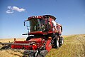
Self-propelled combine harvester at work

Pulled combine harvester


Operation of threshing organs and separation
There are three categories of working method:
- Conventional combine with threshing drum and rack shaker s. Scheme drawing above
- Axial combine without a threshing drum - only rotors do the threshing and separation
- Hybrid combine harvester with threshing drum and rotor
The actual threshing system consists of a threshing drum and a concave. A distinction is made here between four basic concepts.
Tangential threshing system (conventional)
The axis of the threshing drum is perpendicular to the direction of travel in the combine harvester. The flow of the crop is therefore tangential to the drum. Depending on the performance requirements, two or more rotating units are installed. Tangential aggregates are never wrapped around the straw for more than three quarters of a turn. Then the threshed straw leaves the drum again. Not all grains fall through the concave on this short path. So another separation system is needed.
Axial threshing system
With axial threshing units, the axis of rotation of the rotor runs in the direction of travel. The straw is guided around the rotor several times. Slanted plates on the upper inside of the rotor drum cause the thrust to the rear. Therefore, the main flow direction of the crop is along the axis.
The threshing takes place in the front section of the rotor, the separation in the rear section. A compromise has to be found between threshing speed and separation speed. John Deere works here with different rotor / housing diameters in the crop flow. A Russian manufacturer uses rotating baskets. The separation efficiency of rotors is very high. Losses do not increase as much as the throughput increases as with the shaker separation.
Due to the much simpler construction and the resulting cost advantage, this construction has established itself in North and South America as well as in Russia. With the favorable threshing conditions prevailing there, throughputs can be achieved that are only slightly below those of hybrid systems and significantly above those of tangential systems.
The straw is subject to high mechanical stress and can therefore hardly be processed further as long straw.
Transversal threshing system
Functionally, the transverse threshing system is similar to the axial threshing system. A rotor is also used for threshing and separation. However, the axis of rotation lies transversely in the combine harvester. This means that the material to be threshed does not have to be deflected in its natural flow, as happens when an axial rotor is fed. In contrast to the threshing drum, the crop is carried more than one full rotation in the rotor. The transversal threshing system is mainly installed in specialized small combine harvesters for rice threshing (e.g. Claas Crop Tiger). For conventional combine harvesters, the system is only offered by AGCO-Gleaner.
Hybrid threshing systems
With the hybrid threshing system, the crop is threshed in one or more tangential threshing drums and then fed to one or more separator rotors. The separator rotor has the advantage over the shaker that it enables a much more intensive separation of chaff and straw. The disadvantage is that the straw is more stressed and the broken straw is more stressful for cleaning. Therefore, cleaning is the limiting factor on many models. For this reason, the speed of the separator rotors must be adapted to the harvesting conditions in order to find a compromise between separation and cleaning performance.
Separation systems
When it comes to separation, a distinction is made between two fundamentally different types of separation organs.
- Tray shaker: With conventional combine harvesters, separation takes place via a tray shaker. The shaker consists of four to six trays with barb-shaped prongs attached to the top. All trays are attached to two crankshafts that rotate. The result is a circular eccentric movement of the tray: first upwards, then backwards, then downwards, then forwards. When a horde is at the top, the hordes next to it are deepest. On the way up, the hordes take over the straw mat from the one next to it and lead it to the rear with the barbs. When moving downwards, they give the mat back to the trays next to it. Empty they run forward again in the direction of travel.
- As a result, the straw is thrown up in such a way that the grains still carried with it fall through the straw mat. Under each shelf there is a tub on which the grains run diagonally forward onto the preparation floor.
- The shaker is the separation system that puts the least strain on and destroys the straw. The separation efficiency drops quickly with damp or immature straw. When driving uphill, the losses also increase because the slope of the slope opposes the tendency to shake. On the side slope, the tray limits the separation capacity on the underside of the slope. Under these conditions the driving speed must be reduced.
- Axial separation elements : Combines with very wide cutting units are therefore built with axial separation elements. One or two (then arranged side by side) axial rotors take on the task of separation. The centrifugal forces separate the grain and straw from one another. Elements made of a basket structure, which enclose the rotor at least below, prevent too many non-grain components from reaching the cleaning system and thus limiting its functionality. With axial systems, the straw passes through the separation around ten times faster than with shaker systems. Therefore, higher throughputs are possible and the grain loss is significantly lower, especially in wet harvesting conditions. Axial combine harvesters are also less susceptible to steep slopes, since gravity is less important for separation.
Slope combine harvester
As a rule, grain is grown on flat surfaces. However, there are regions where threshing crops are grown in gently hilly to sometimes quite steep topographies. As described above, the threshing and separating process in combine harvesters is very much influenced by the topography or the force of gravity. The fact that the threshing unit is fed on one side due to the incline of the slope reduces the machine's performance enormously, as the entire width of the threshing unit is not used. Worse, however, is the one-sided loading of the cleaning system (preparation floor, sieves) with the threshed goods. Chaff and grain reach the cleaning system on the downhill side, and the sieve movement further concentrates the material on one side.
The performance penalty increases exponentially with the slope. So it is of great interest, the slope respectively. to compensate for this performance degradation. There are various systems for this.
Slope chassis

The oldest method that is still used today, especially on extreme slopes, is that the chassis is raised or lowered so that the threshing elements are horizontal. The first combine harvester with slope compensation based on this principle was built in 1891 by the Holt brothers in California. The slope compensation had to be set mechanically on earlier machines, which required a second person on the combine. The first automatic slope compensation was developed by Raymond A. Hanson in 1941. In 1945 he equipped the first machines with this system, in which the degree of inclination was determined using mercury switches and the separating elements were aligned accordingly using pneumatic cylinders.
Today, compensation is usually done using two hydraulic cylinders that lift the combine harvester on one side from the front axle and thus hold it horizontally. Since the rear axle is pivoted, no inclination compensation is required. More rarely, lifting hydraulics on the rear axle also enable inclination compensation in the longitudinal direction.
The technical effort and the associated costs are problematic here. The transfer of crops from the inclined cutterbar to the straight combine harvester is also problematic. However, this system has the advantage that the entire vehicle, with the exception of the cutting unit, is held horizontally. The performance of the cleaning organs is thus not impaired by lying on the side. The volume of the grain tank can also be fully used, which is not possible if the vehicle is tilted to one side, as the crop would slip to this side, which in extreme cases can even result in the vehicle tipping over. In addition, the driving comfort is increased, since the driver also remains in a straight sitting position and does not threaten to slip out of the seat.
Transverse sheets
As another very simple system, cross plates have established themselves on the sieves, which only allow the goods to slide to the slope side to a limited extent.
Slope compensation
As a further solution, Claas relies on slope compensation. The slope inclination is measured and the sieves are set in a transverse oscillation dependent on the inclination via a hydraulic actuator. As a result, the material is conveyed uphill against gravity and thus distributed evenly. New Holland also offers slope compensation systems which, depending on the slope, which is determined by an electronic spirit level, hold the entire cleaning process (sieve box and fan) in a horizontal position by means of an electric spindle motor. Both systems only compensate for lateral inclinations of the machine.
Rotary combine harvester
Rotary combine harvesters have fewer problems with the slope due to the way they work; if cleaning is also carried out in a rotary manner, slope compensation is not necessary. Larger combine harvesters are mainly offered in this design.
Manufacturer

The corporate concentration that has taken place in many areas in recent years can also be observed in the agricultural sector. With combine harvesters, the high technological requirements and capital-intensive production also contribute to the fact that many formerly independent companies are now united in one umbrella group . Established brand names are sometimes retained side by side or - for example regionally or in the product range - differentiated. While lesser-known or respected brands are being given up, companies with a high-quality image can take over previously non-existent product lines under their own names from sister companies.
- John Deere is the world leader in agricultural machinery.
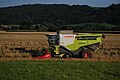
- Claas is the European market leader for combine harvesters.
- In the CNH Industrial group, the world's second largest agricultural machinery manufacturer, the GDR brand progress , among other things, went on, today's brands are
- Case IH and
- New Holland .
- AGCO ( Allis-Gleaner Corporation ), formed in 1990, combined a number of well-known brands:
- Gleaner has been the brand name for harvesters from the start.
- Massey Ferguson was acquired in 1994.
- Fendt joined the group in 1997 and has been selling combine harvesters under its own name since 1999.
- Laverda has been wholly owned by the group since 2010.
-
SDF sells combine harvesters under the brand:
- Deutz-Fahr is the successor company to the first German manufacturer.
- Gomselmash is a Belarusian manufacturer of u. a. Combine harvesters.
- Rostselmasch is a Russian manufacturer of u. a. Combine harvesters.
- Sampo Rosenlew is a Finnish manufacturer of u. a. Combine harvesters.
The company Zürn Harvesting , which the company Hege bought from the inventor of this type of combine, Hans-Ulrich Hege , and Wintersteiger produce plot threshers for testing purposes .
Trivia
On the back of the 5- Mark (DDR) banknotes a combine harvester of the type Progress E 512 was depicted.
literature
- Udo Bols: Combine harvesters in Germany from 1931 to today . 3 volumes, Podszun, Brilon 2005-2008, ISBN 978-3-86133-406-4 .
- Dr. Klaus Krombholz, Dr. Hasso Bertram and Hermann Wandel: 100 years of agricultural engineering - from handcraft to high-tech in Germany . DLG-Verlag, Frankfurt am Main, 2009, ISBN 978-3-7690-0737-4 .
- Graeme R. Quick, Wesley F. Buchele: The Grain Harvesters. American Society of Agricultural Engineers, St. Joseph / Michigan 1978, ISBN 0-916150-13-5 .
- Manfred Baedecker, Ralf Lenge: The Claas combine harvester story . Landwirtschaftsverlag, Hiltrup 2001, 2nd edition 2003. ISBN 3-7843-3053-3 .
Web links
Individual evidence
- ^ Paul Schweigmann: The agricultural machines and their maintenance . 1st edition, Pfanneberg, Gießen 1955, reprinted by Bulldog-Press, Limburg ad Lahn 1993, ISBN 3-9803332-1-3 , pp. 196-197
- ↑ Horst Eichhorn, Landtechnik, 7th edition, Ulmer, Stuttgart, 1952, 1999, ISBN 3-8001-1086-5 , p. 259 f.
- ↑ Fendt Ideal technical data . AGCO / Fendt , August 2, 2019
- ^ Claas Lexion 8000 . Claas , August 2, 2019
- ↑ http://www.cornways.de/hi_combine.html
- ↑ Archived copy ( memento of the original from September 29, 2008 in the Internet Archive ) Info: The archive link was inserted automatically and has not yet been checked. Please check the original and archive link according to the instructions and then remove this notice.
- ↑ Archived copy ( memento of the original from September 29, 2008 in the Internet Archive ) Info: The archive link was inserted automatically and has not yet been checked. Please check the original and archive link according to the instructions and then remove this notice.
- ↑ M. Baedecker, R. Lenge, pp. 13 + 14
- ^ Paul Schweigmann, The agricultural machines and their maintenance, 1st edition, Pfanneberg, Gießen, 1955, reprinted by Bulldog-Press, Limburg ad Lahn, 1993, ISBN 3-9803332-1-3 , p. 280 ff.
- ↑ Archived copy ( memento of the original from September 29, 2008 in the Internet Archive ) Info: The archive link was inserted automatically and has not yet been checked. Please check the original and archive link according to the instructions and then remove this notice.
- ↑ Archived copy ( memento of the original from September 29, 2008 in the Internet Archive ) Info: The archive link was inserted automatically and has not yet been checked. Please check the original and archive link according to the instructions and then remove this notice.
- ↑ www.zuern.de
- ^ The Zürn company takes over the production of the Hege parcel threshers
- ↑ www.wintersteiger.com ( page no longer available , search in web archives ) Info: The link was automatically marked as defective. Please check the link according to the instructions and then remove this notice.