Brayton engine
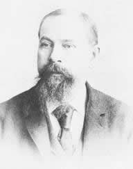
A Brayton Cycle engine , known in English as a Brayton's Ready engine is a combustion engine , according to one of the Brayton cycle working approximate method. The Brayton engine is named after and invented by George Brayton . Brayton engines are designed as reciprocating piston engines and require at least two cylinders, since at least one cylinder always serves as a combustion cylinder and at least one cylinder as an expansion cylinder.
history
Brayton applied for a patent for the Brayton motor in 1872. Originally the Brayton engine was a gas engine; its efficiency is better than that of a Hugon engine , but worse than that of a classic Otto engine . In 1874, Brayton was granted a patent for a fuel injection system to burn liquid fuels such as crude oil and petroleum. From 1876 Brayton marketed the engine commercially; In 1878 he exhibited it at an exhibition in Paris. However, the Brayton engine has never played an important role in engine construction due to its poor efficiency. Only the air injection of the fuel that was used was able to find a certain widespread use in diesel engine construction, since diesel, lacking its own solution for an injection system, used an air injection similar to Brayton's air injection, but with significantly higher pressures.
- US125166, gas engine with single-acting cylinder
- US151468, engine with single-acting cylinder for liquid fuels
functionality
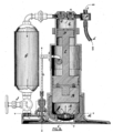
In a Brayton engine there is an expansion cylinder and a compression cylinder as well as a separate mixture boiler. The cylinders have the same bore, but the piston in the expansion cylinder has a double stroke. Although the Brayton engine maps all four work cycles of an internal combustion engine, intake, compression, work, exhaust, but due to the design, two work cycles always take place at the same time, which is why the Brayton engine is counted as a two-stroke engine. As in modern internal combustion engines, the pistons are single-acting. The Brayton engine is spark-ignited and valve-controlled, each cylinder has one inlet and one outlet valve; With the exception of the outlet valve of the compression cylinder, which is controlled by overpressure, all valves are poppet valves with a conical seat and are operated via cams and rocker arms.
During the expulsion work cycle of the expansion cylinder, a charge consisting of fuel and air is sucked into the compression cylinder and then compressed in a separate mixture boiler. The pressure in this vessel is approximately 60–80 lbf · in −2 above atmospheric pressure (515–653 kPa). The mixture is ignited in the expansion cylinder when it leaves the mixture boiler and expands there until it reaches atmospheric pressure and reaches the exhaust pipe.
The ignition system of the Brayton engine is based on a permanently burning flame. For this purpose, a bypass is installed next to the inlet valve, into which finely perforated brass plates with a metal sieve are inserted. This bypass allows fuel to flow continuously into the combustion chamber without having to go through the inlet valve. To start the engine, a plug is pulled and the fuel is set on fire on the metal sieve. The fact that there is always fuel that flows through the bypass means that the flame in the combustion chamber does not go out. When the inlet valve is opened, a large amount of the mixture of fuel and air enters the expansion cylinder, which is ignited by the flame. The metal plates in the bypass are intended to prevent the flame from striking back into the mixture boiler, where the mixture would ignite in an uncontrolled manner, which would destroy the engine.
To avoid the problem of possible engine damage, Brayton converted the engine to run on petroleum. To do this, he connected a petroleum pump to the bypass, which pumps a suitable amount of petroleum onto the metal sieve. In the mixture boiler, only air is now compressed, which, due to the changed valve timing, mainly pushes through the metal sieve and thus entrains and finely atomizes the kerosene so that it can burn in the expansion cylinder. The heavy sooting of the combustion chamber, which made regular cleaning necessary, proved to be a disadvantage.
Technical data (according to Professor Thurston, 1873)

| size | Imperial | Metric |
|---|---|---|
| Cylinder bore | 8 in | 203.2 mm |
| Medium piston speed | 180 ft min −1 | 91.5 cm s −1 |
| Effective medium pressure | 33 lbf in −2 | 0.2275 MPa |
| Estimated gross output | 5 bhp in size | 3730 W. |
| Actual gross output | 8.62 bhp tall | 6430 W. |
| Net power | 3,986 bhp | 2970 W |
| Fuel consumption | 69.3 ft 3 bhp −1 h −1 | 2.64 m 3 kW −1 h −1 |
| Source unless otherwise stated | ||
Media on Wikimedia Commons
literature
- Dugald Clerk: The Gas, Petrol and Oil engine , Volume 1, new and revised edition, Longmans, Green & Co, London 1910, pp. 20-29
- Colin R. Ferguson, Allan T. Kirkpatrick: Internal Combustion Engines: Applied Thermosciences , 3rd Edition, John Wiley & Sons, 2015, ISBN 978-1-118-53331-4 , p. 4
- Sass, Friedrich: History of the German internal combustion engine construction from 1860 to 1918 , Springer, Berlin / Heidelberg 1962, ISBN 978-3-662-11843-6 , pp. 413-415
- Hellmut Droscha, in MAN Nutzfahrzeuge AG (Hrsg.): Achievement and way: On the history of MAN commercial vehicle construction, Springer, Berlin / Heidelberg 1991, ISBN 978-3-642-93490-2 . P. 417
Remarks
- ↑ The piston area is given in the source, it is 50.26 in². The following calculation gives the bore: 2 × ((50.26 / π) ^ 0.5)
Individual evidence
- ↑ https://patents.google.com/patent/US125166
- ↑ a b Clerk 1910, p. 20
- ↑ https://patents.google.com/patent/US151468A
- ↑ Sass 1962, p. 415
- ↑ Clerk 1910, p. 21
- ↑ Clerk 1910, p. 22
- ↑ Clerk 1910, p. 23
- ↑ Clerk 1910, p. 24
- ↑ a b https://archive.org/details/cu31924004083345/page/n41
- ↑ https://archive.org/details/cu31924004083345/page/n37
- ↑ Clerk 1910, p. 25
- ↑ Clerk 1910, p. 26


