Air injection
The process of air injection is historically the first form of internal mixture formation for combustion engines, which made the technical realization of the diesel engine possible from 1896 . The fuel is blown into the combustion chamber with compressed air. The required compressed air is generated with a compressor . The inventor of air injection is George B. Brayton .
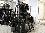
The technique allowed the time only low speeds to about 360 min -1 , so the engine performance with high torque has been achieved and a corresponding amount of displacement, so with large and heavy machinery. It also requires a complex high-pressure compressor with over 50 bar and a compressed air tank . Because of their size, motors with air injection are practically only suitable for stationary or marine propulsion . A simple fuel metering pump , which had to overcome the pressure of the compressed air at most, was sufficient for air injection . Injection pumps , whose injection pressure was sufficient to atomize the fuel directly and finely enough, were not implemented until 1909 with the introduction of pre-chamber injection , which also enabled high-speed diesel engines for rural vehicles and thus quickly displaced air injection from the 1920s.
history
Air injection was first used in a gas engine by George Brayton in 1872 . Rudolf Diesel intended to build an engine with direct injection , for which he first used the accumulation process in 1893, i.e. the fuel was pressurized (with compressed air) in a container and then injected into the cylinder at the right time. Because of the high viscosity of the fuels used by diesel and insufficient combustion properties, the accumulation did not work satisfactorily. Diesel therefore had to improve its injection system and, in 1894, replaced the accumulating vessel with the Brayton air injection system. Nevertheless, Diesel wanted to find a better solution because he was dissatisfied with the air injection. Together with Rudolf Brandstettder , Diesel received a patent in 1905 for an improved accumulation system, which, however, did not work well enough, so that Diesel finally described direct injection as “impracticable”; the technically possible injection pressures of the injection pumps were too low for the necessary fine atomization. In order to reduce the required injection pressure, Prosper L'Orange invented the prechamber , in which the combustion chamber and injection chamber are separated from each other. This system manages without high injection pressure and without air injection, but it has the disadvantage of lower efficiency. With indirect injection nevertheless laid the foundation for building diesel engines so compact that they also land motor vehicles can be used. The first compressorless direct-injection diesel engine for vehicles was the MAN W 4 V 10/18, of which three prototypes were built between 1923 and 1925. This made the air injection obsolete.
construction
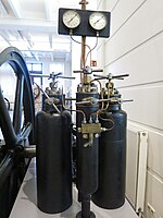
The system consists of one or more compressed air tanks ( injection bottles ) that feed the controlling injection valve in the cylinder head via a line that is constantly under pressure . The compressed air reserve is usually topped up to the required injection pressure by a high-pressure compressor driven by the engine's crankshaft . The usually larger reserve capacity of the compressed air tank is used to start the engine.
Injector systems
There is a closed and an open system for the injection nozzles:
Closed injection system
The closed system is the older and much more common system, mainly with stationary engines (such as the Langen & Wolf engine in the picture on the right). It can be used for both two-stroke and four-stroke engines. The fuel pump delivers the fuel to the injection nozzle while the compressed air is pressed to the injection nozzle at the same time. The fuel pump must therefore work against the compressed air. If the injection valve is now actuated by the camshaft, the fuel is pressed into the combustion chamber by the compressed air. Before the injection valve opens, neither fuel nor compressed air enter the combustion chamber. The advantage of the closed system is the good distribution of the fuel in the combustion chamber, which is why it is particularly suitable for large-volume engines. The good atomization of the fuel results in lower fuel consumption than with the open system. Disadvantages are the high production costs and the increased effort in the construction of the fuel pump, since it has to deliver against excess pressure. In addition, it is technically difficult to build a closed-system engine horizontally because the air can enter the combustion chamber without forcing sufficient fuel into it, which can lead to misfiring and retarded ignition.
Open injection system
In the open system, which is almost only used in horizontal engines, the fuel circuit is connected to a chamber in front of the combustion chamber, which is above the main combustion chamber. In between are Plättchenzerstäuber installed. In this design, the fuel pump does not deliver against the compressed air, but fills the upstream chamber with low pressure before the compression stroke of the piston. It can only be used for four-stroke engines. However, as in the closed system, the compressed air is controlled by the injection valve. When the injection valve opens, air is pressed into the combustion chamber, which takes the fuel with it from the upstream chamber. The open design is easier to adapt to horizontal engines and, above all, cheaper to manufacture and better suited for operation with tar oil . Furthermore, the fuel pump can be constructed more simply, since it only has to deliver against low pressure. The disadvantage is the less favorable fuel distribution in the combustion chamber: At the beginning of the injection process, too much fuel usually reaches the combustion chamber. As a result, the working pressure is massively increased when combustion begins, which has an adverse effect on the service life. The combustion process approaches that of a gasoline engine . Furthermore, the correct amount of fuel cannot be properly measured for larger engines, so this system is only suitable for smaller engines.
Blowing process
With each injection, around 3% fuel and 97% air (in each case volume percent) are blown in, the air being under a pressure of approx. 5–7 MPa (50–70 bar).
The injection pressure limits the speed , since the faster the engine runs, the higher it has to be in order to complete the injection process more quickly against increasing compression pressure and to prevent misfiring. Since the injection pressure depends directly on the compressed air tank, it can only be adjusted slowly : the speed can only be changed slowly; only the torque (the load) can be controlled with the amount of fuel injected ( qualitative mixture regulation ). The constant speed operation is particularly suitable for stationary engines , power generators and ship propulsion systems.
Atomizer types
The injection nozzles have a so-called atomizer for atomizing the fuel. Sieve atomizers were originally used before they were replaced by plate atomizers. There were also ring or block atomizers as additional designs.
- The ring atomizer is based on the principle of the speed difference between the air at different points in the injection nozzle, i.e. the fuel is atomized pneumatically.
- With the platelet atomizer , perforated platelets are used on the injection nozzle needle, which atomize the fuel through their mutually offset holes when the air pressure acts (see Figure 6 in the drawing top right). Depending on the displacement and the amount of fuel injected, between two and four atomizer plates were used. The material depends on the fuel. Bronze and phosphor bronze were commonly used, while tar oil engines often used steel.
Neither the calculation of the correct dimensions of the injection nozzle diameter nor the correct choice of the atomizer plate hole size was known at the beginning of the 20th century, the designs were based solely on practical experience. Hole diameters that are too large require too much air pressure and thus compressor and ultimately engine power, while a hole diameter that is too small reduces engine power. Julius Magg recommended to set the narrowest hole diameter based on the indicated engine power: . corresponds to the hole diameter, the engine power in hp.
disadvantage
The greatest disadvantage of air injection is the large number of large and complex components that are necessary for the operation of the engine.
- In particular, the maximum speed of an air injection motor of up to 360 min −1 is not very high, which is why it has to deliver high torque with large dimensions in order to achieve its performance.
- Dynamic load changes are hardly possible.
- The air compressor consumes part of the engine power.
advantages
- Engines with a closed injection system achieved low fuel consumption by the conditions of the time around 1900 thanks to the almost ideal fuel atomization.
- With a larger air supply, the required compressed air system can also advantageously be used to start the engine, since engines with more than 10 kW of power can no longer be started with muscle power. There is no need to use an electric starter with accumulators for starting.
Remarks
- ↑ a b Julius Magg describes in his work The Controls of Internal Combustion Engines technical aspects of engines with nominal speeds of 160, 167, 210, 250, 300 and 360 min -1
- ↑ a b The engine power is calculated using the following formula: , in kW, m N x, in min -1
- ↑ The first functional diesel engine has a specific fuel consumption of 324 g / kW · h. (Cf. Günter Mau: Handbuch Dieselmotoren im Kraftwerks- und Schiffsbetrieb , Vieweg, Braunschweig / Wiesbaden, 1984, ISBN 978-3-528-14889-8 . P. 7)
Individual evidence
- MAN Nutzfahrzeuge AG: Performance and path: On the history of MAN commercial vehicle construction. Springer-Verlag. Berlin, Heidelberg. 1991. ISBN 978-3-642-93490-2 .
- Rüdiger Teichmann, Günter P. Merker (Ed.): Fundamentals of internal combustion engines: functionality, simulation, measurement technology , 7th edition, Springer, Wiesbaden, 2014, ISBN 978-3-658-03195-4 .
- Friedrich Sass: Building and Operating Diesel Engines: A Textbook for Students. First volume: Fundamentals and machine elements , 2nd edition, Springer, Berlin / Heidelberg, 1948, ISBN 9783662004197 .
- ↑ p. 94 ff.
- Julius Magg : The controls of the internal combustion engines . Springer publishing house. Berlin. 1914. ISBN 978-3-642-47608-2 . Pages 261-281.
- Anton Pischinger, Otto Cordier: Mixture formation and combustion in the diesel engine . Jumper. Vienna. 1939. ISBN 978-3-7091-9724-0 .
- ↑ p. 1
- Otto Kraemer , Georg Jungbluth : Construction and calculation of internal combustion engines . Springer publishing house. Berlin, Heidelberg. 1983. ISBN 9783642932410 .
- ↑ p. 64


