JGR class 7000
| JGR 7000 JGR ED54 |
|
|---|---|
|
Drive side of the 7001
|
|
| Numbering: | 7000-7001 54-1-54-2 |
| Number: | 2 |
| Manufacturer: | SLM Winterthur, BBC Baden |
| Year of construction (s): | 1926 |
| Retirement: | 1948 |
| Axis formula : | (1A) Bo (A1) |
| Gauge : | 1067 mm ( cape track ) |
| Length over coupling: | 13,600 mm |
| Height: | 3920 mm |
| Width: | 2950 mm |
| Fixed wheelbase: | 1900 mm |
| Total wheelbase: | 9900 mm |
| Service mass: | 78.05 t |
| Friction mass: | 59.75 t |
| Wheel set mass : | 15.2 t |
| Top speed: | 100 km / h |
| Hourly output : | 1540 kW (2039 hp ) |
| Hourly traction: | 80 kN (8,200 kg) |
| Driving wheel diameter: | 1600 mm |
| Impeller diameter: | 940 mm |
| Power system : | 1500 V DC |
| Number of traction motors: | 4 × MT20 |
| Drive: | Buchli drive |
| Translation levels: | 1: 3.35 |
| Brake: | Compressed air brake EL14A |
| Control: | Cam switch |
| Coupling type: | Janney clutch |
Class 7000 , known as ED54 from 1928 , was an express locomotive of the Japanese Government Railways (JGR) with Buchli drive . The two locomotives of this series were only in use for a good twenty years because the railway could not cope with the maintenance of the drives, which were only used on these two locomotives.
history
Until the 1930s, Japan imported all locomotives from western countries. In addition to locomotives from American and British manufacturers, locomotives were also imported from Switzerland. These were two class 1020 freight locomotives and the two class 7000 express locomotives. The mechanical part of the locomotives was manufactured by SLM in Winterthur and had the serial numbers 3040 and 3041, the electrical part came from BBC in Baden .
commitment
The locomotives were used on the Tōkaidō main line . The locomotive proved itself in operation because of its high performance and better running properties compared to the locomotives with a pawl bearing drive . However, because only two locomotives of this series were available, the possibilities for use were limited and the effort involved in training the staff was great. The maintenance of the splinter class was costly. so that the number of operations decreased and a mileage of only 180 km was achieved within 6 months.
In the 1930s, the Japanese industry began to build its own locomotives in large numbers, so the ED 54 was shut down. The locomotives were retired in November 1948. The ED54-2 was stored in the Ōmiya depot for a long time with the intention of keeping the locomotive in a railway museum, but was canceled in the mid-1960s. So neither of the two locomotives has survived.
technology

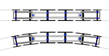
As with all Buchli-powered locomotives, the left and right sides of the locomotive had a very different appearance. The locomotive was designed with a load-bearing floor frame on which the devices were arranged. The locomotive body was formed by the three removable hoods over the engine room and the two end cabs . In front of each driver's cab there was a small open platform with the option of passing to the neighboring passenger car. The entrance to the driver's cab was through a door in the front on the companion's side. The drive switch was located on the left-hand side in the direction of travel.
On the drive side, the Buchli drives were arranged in front of the large drive wheels, above that in the engine room were the side aisle and the traction motors . A radial fan was installed above each drive motor for cooling . The starting resistor , the cam switch mechanism and the converter group were located on the non-drive side . These devices were accessible through maintenance hatches in the side wall.
The chassis consisted of two Java bogies and two movable central axes, which gave the locomotive optimal cornering.
Electrical equipment
The electricity was taken from the catenary via two BBC pantographs of type PS 5. The pantograph had only one contact strip.
The quick switch could be opened via an electro-pneumatic valve or by hand. The overload relay opened the high-speed switch automatically. The extinguishing of the arc was supported by two blow coils and a current sink resistor.
For the staff it was unfamiliar that both the lever of the reversing switch and that of the main switch had to be removed and taken with them when changing the cab. Each of these handles was made of bronze and weighed 600 g. The electrical voltage of the control power network was 100 V.
See also
literature
- FJG Haut: The pictorial history of electric locomotives . AS Barnes, South Brunswick NJ 1969, ISBN 0-498-07644-X , pp. 90 .
Web links
- ス イ ス 製 の ED12 ・ ED54 電 気 機関 車 'Swiss electric locomotives ED12 and ED54' . Retrieved January 6, 2018(Japanese).
Individual evidence
- ^ Kaspar Vogel: The Swiss Locomotive and Machine Factory 1871-1997 . 2nd expanded edition. Minirex, Luzern 2003, ISBN 3-907014-17-0 , p. 213 .
- ↑ a b ス イ ス 製 の ED12 と ED54 電 気 機関 車 (日 高 冬 比 古 の 電 気 機関 車 発 達 史 3). Retrieved January 6, 2018 .


