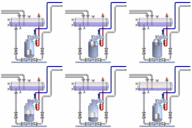
Condensate lifter
Pump Trap lift in plants accumulating condensate from the lowest point, where it is generated, again to a certain level, where it can be recycled.
functionality
In principle, the condensate lifter works instead of a pump, but is to be understood as a higher-quality replacement for this. The condensate flows to the condensate lifter from an upstream collecting tank, busbar or consumer via its suction line. These containers are much smaller than in conventional pump systems.
As the liquid level in the condensate siphon rises, the built-in float moves upwards and, in its high position, activates the externally blocked control via a switching ring after it has reached its full buoyancy. The steam inlet valve opens, the non-return valve in the suction line closes with easy and noiseless contact. The funding process is now initiated.
The pressure in the condensate lifter builds up independently of the motive steam or working steam pressure at the level of the pressure in the pressure line, the condensate is displaced. Due to thermodynamic installations, the steam hits the liquid column in the working space of the condensate siphon in an extremely elastic manner through pressure and temperature stratifications (initially relaxed steam is compressed again), which means that the pumping process is almost noiseless (slight flow noise) and, above all, without impact.
As the condensate level in the condensate lifter sinks, the built-in float slides downwards and in its end position actuates the control again via the lower switching ring, which closes the steam inlet valve and opens the expansion valve. The residual steam is fed into the collector via the connected ventilation or expansion line with a simultaneous subsequent flow of condensate. This ends one work cycle and the next begins.
The condensate lifter works as long as condensate is available and stops automatically if no condensate flows in. It starts to work again immediately when condensation occurs again or works in this way continuously, depending on the amount of condensation, in continuous operation. The cycle time is around 40 seconds, with the feed times in relation to the conveying process being around 2: 1.
Areas of application
- Power plant technology
- Turbine drainage
- Air preheating
- Waste heat boiler
- Auxiliary systems
- Refineries
- Single and ring systems
- Product promotion
- Condensate return
- Chemical industry
- High and low pressure condensates
- Route drainage
- Process fluids
- Flare gas drainage
- Benzol production
- Other industries
- Paper industry
- Sugar industry
- Breweries
- Rubber works
- Food industry
- Micro-industry
