Cross connection

The cross connection is an electrical circuit in electrical installations with which a consumer can be switched on and off at more than two switch positions. Consumers are mostly lighting systems, for example in hallways. If only two switches are required to switch the lamp, the corresponding simplification results in the changeover switching .
Layout and function
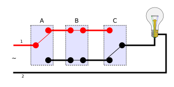
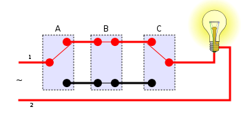
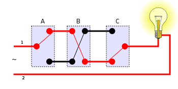
With cross switching , two toggle switches are set at the beginning and end of the chain and any number of cross switches in between. The cross connection is therefore an extension of the changeover circuit, with each crossover switch being able to interchange the two corresponding lines of the original changeover circuit.
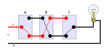
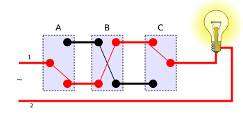
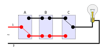
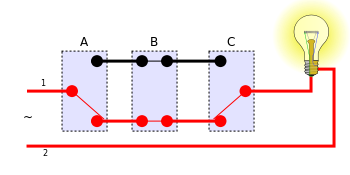
A cross switch contains two mechanically connected single-pole changeover switches, which are connected in such a way that an actuation between a straight connection between two pairs of terminals (left 1 ↔ right 1 and left 2 ↔ right 2) results in a crossed connection (left 1 ↔ right 2 and left 2 ↔ right 1) can be changed.
The switches are each connected with two wires, one or the other of which is always live - depending on the switching status of the individual switches - and the other is not. When any switch is operated, the continuing wires swap their state - in the sense of Boolean logic , both "signals" are negated: from ON to OFF and vice versa.
The first or last switch can, but does not have to be, a cross switch, as a cross switch can always function as a toggle switch if a connection remains unoccupied. At the first changeover switch it is possible - if installed with remote junction boxes - to add a socket outlet to the circuit if a 5-core cable is laid; sockets must be supplied separately for all other switches. If switch junction boxes are used, a 5-core cable is sufficient: a socket can then be installed at each switch.
The color of the outer conductor L is brown according to the standard (previously black). Blue wires may only be used for the unswitched neutral conductor due to the risk of confusion . The color green-yellow is reserved for the protective conductor . The corresponding wires can - except for the reserved ones - have any color.
An alternative to the cross connection is the impulse circuit (also called push button circuit), which is often cheaper to implement than the cross connection.
The eight possible combinations of toggle switches A and C and cross switch B in a cross connection
| Out | On |
|---|---|
 |
|
 |
|
 |
|
 |
|
Comparison of cross connection and push button connection
In general, the following applies: the more switching points, the more preferable it is to switch to a push button . With three switching points, the advantage is usually in the case of cross switching, if no time switch is required.
Disadvantages of the cross connection
- For a cross connection, a continuous pair of wires is required across all switches, which makes expansion difficult.
- Cross switches are more expensive than simple switches or buttons.
- The defective switch leads to the failure of the entire switching process.
- A cross switch requires a four-wire line, whereas a button only requires a two-wire line.
- In contrast to the push-button circuit, the automatic switch-off after a certain time (staircase lighting) is not easy to implement.
Advantages of the cross connection
- No impulse switch is required. This can compensate for the higher price for the switches, especially with only three switches.
- When using the particularly widespread five-core cable (with protective conductor ), a later switch to push-button switching allows socket outlets to be installed later without having to replace the cable.
See also
literature
- Winfrid Hauke, Rolf Thaele, Günter Reck: RWE Energie Bau-Handbuch. 12th edition. Energie-Verlag, Heidelberg 1998, ISBN 3-87200-700-9 .
- Günter Springer: Expertise in electrical engineering. 18th edition. Europa-Lehrmittel, Wuppertal 1989, ISBN 3-8085-3018-9 .
Individual evidence
- ↑ Meis Eric: Praxis Elektroberufe / Pratique métiers de l'électricité . Epubli, Berlin 2013, ISBN 978-3-8442-8533-8 , p. 96.
- ^ A b Hermann Merz, Thomas Hansemann, Christof Huebner: Building automation. 3rd, updated edition. Carl Hanser Verlag, Munich 2016, ISBN 978-3-446-44662-5 , ( excerpt ).
- ^ Otto Haack: Introduction to digital technology. 4th edition. BG Teubner Verlag, Stuttgart 1984, p. 78.
- ↑ a b c Horst Gebert, Gregor Häberle, Hanswalter Jöckel, Thomas Käppel, Jürgen Schwarz: Technical communication electrical engineering. 8th, revised and expanded edition. Verlag Europa-Lehrmittel, Haan Gruiten 2014, ISBN 978-3-8085-3258-4 , pp. 16-18.
- ↑ Hans-Joachim Adam, Mathias Adam: PLC programming in instruction list according to IEC 61131-3. 5th edition. Springer-Verlag, Berlin / Heidelberg 2015, ISBN 978-3-662-46715-2 , pp. 32–33.
- ↑ Duewi installation plans p. 04 (accessed on January 5, 2018)
- ↑ a b c Andreas Burgwitz: Modern electrical installations . Compact Verlag, Munich 2009, ISBN 978-3-8174-2085-8 , pp. 16-18.
- ^ Hans-Jürgen Reinbold, Karl-Gerhard Haas: Repairs at home. The book for the toolbox. 4th edition. Stiftung Warentest, Berlin 2013, ISBN 978-3-86851-073-7 , pp. 236-238.
Web links
- Advantageous installation - components for electrical installation . Brochure from an impulse switch manufacturer (accessed January 5, 2018)

