Digital cross connection
A digital cross connection is a cross connection that is implemented with logic gates .
With a cross connection, a switching process can be carried out independently of one another by three or more switches, for example switching a lamp on and off. Only the version with three switches is dealt with here.
Truth table
| Switch A | Switch B | Switch C | Lamp L |
|---|---|---|---|
| 0 | 0 | 0 | 0 |
| 0 | 0 | 1 | 1 |
| 0 | 1 | 0 | 1 |
| 0 | 1 | 1 | 0 |
| 1 | 0 | 0 | 1 |
| 1 | 0 | 1 | 0 |
| 1 | 1 | 0 | 0 |
| 1 | 1 | 1 | 1 |
If all three switches are in the zero position, then the lamp is off (even number - zero switches are in the one position). If only one of the three switches is in position one, then the lamp is switched on (uneven number). If two switches (even number) are in position one, the lamp is off. If, however, three switches (uneven number) are in position one, the lamp is on. The associated truth table is on the right. It is practically a test of the odd number of ones. If the number of switched on switches is uneven, the circuit is closed.
Karnaugh-Veitch diagram

The disjunctive normal form (DNF) can be read from the truth table . Only the lines in which the result is one (marked in red in the table) are read, i.e. the 2nd, 3rd, 5th and 8th lines. Where there is a one for the input values A, B and C, the variable is accepted unchanged, while where there is a zero for the input values, the negated form of the variable is accepted (character: "¬"). Example: the second line (marked in green) reads A = 0, B = 0, C = 1, this becomes: ¬A ∧ ¬B ∧ C. The logical expressions of the individual lines are linked with a logical OR (character: " ∨ "). Usually, the AND operators (character: “∧”) are not written down for the sake of simplicity, so that ¬A ∧ ¬B ∧ C means the same as ¬A¬BC.
The disjunctive normal form of the digital cross connection is:
¬A¬BC ∨ ¬AB¬C ∨ A¬B¬C ∨ ABC.
The DNF is entered in the Karnaugh-Veitch diagram (KV diagram) in order to reduce the logical expression to its minimal form (Fig. 1). Since in this case the ones fields are not next to each other, but only touch at the corners, no groups of two can be formed. In this case, the term cannot be shortened any further. The DNF is also the Minterm .
Digital circuit
With AND, OR and NOT gates
Figure 2 shows the implementation of the digital cross connection (¬A¬BC ∨ ¬AB¬C ∨ A¬B¬C ∨ ABC) with AND , OR and NOT gates .
With NOR gates
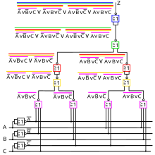
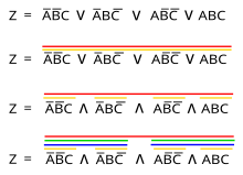
Figure 3 shows the conversion to NOR , since in practice digital circuits are very often implemented exclusively with NOR gates or with NAND gates .
De Morgan's laws are used for the conversion :
- or
and the targeted use of double negation : ¬¬ (ABC) = ABC.
Figure 4 shows the corresponding implementation of the digital cross connection with NOR gates .
With NAND gates
Figure 5 shows the conversion to NAND, since in practice digital circuits are very often implemented exclusively with NOR gates or with NAND gates .
Figure 6 shows the corresponding implementation of the digital cross connection with NAND gates .


