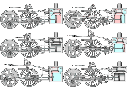
Scenery control

A gate control is a transmission element used in mechanical engineering , with the help of which the gas exchange of certain reciprocating piston engines that work on the principle of external combustion can be changed. This enables the direction of rotation to be reversed during operation and thus to change from a forward gear to a reverse gear and vice versa. The power transmission is controlled by means of a so-called link guide.

application
Link controls are used in particular in steam-powered machines such as locomotives, ships or cranes , which require a reversal of movement during operation and in which there is no need for a separate gearbox or a detachable clutch .
functionality
The backdrop has a slot, web or a groove. In or on the backdrop there is a sliding block, positively guided on both sides, to which the motion of the backdrop is transmitted.
Because different positions of the sliding block can be selected in the gate, the control function affects both the direction of rotation of the machine and its efficiency. The possible positions of the sliding block are determined by the course of the slot, web or groove. The link guide is used in particular to implement complex transfer functions.
An early control of this type that was particularly widespread in the 19th century is the “Stephenson backdrop control”. It was invented to control steam engines by James Howe and William Williams, who worked for the steam locomotive designer Robert Stephenson and Company , patented in 1842 and improved in the following years:
On the axis shown in the sketch with A, two eccentrics E and E1 are attached to each other on the axle shaft at a certain angle. By means of two eccentric rods B and B1, these are connected to the upper or lower end of the curved link KK, which are suspended at the lower end with two rods on the three-armed reversing lever U-U1. Inside the backdrop K is an arcuate slot in which there is a block. This so-called sliding block KS moves the push rod ST used for movement and thus actuates the control slide . With the hand lever H, which moves back and forth on the toothed grid arch H1, the link can be raised and lowered in order to reverse the machine for forward or backward movement as desired.
See also
literature
- William Stuart Auchincloss: The practical application of the slide valve and link motion to stationary, portable, locomotive, and marine engines: with new and simple methods for proportioning the parts. Van Nostrand, New York 1870. (German: The practical application of slide and coulisse controls . Authorized German translation and adaptation by A. Müller. Springer, Berlin 1886)
