Shadow construction
In descriptive geometry , shadow constructions are used to make the representation of spatial objects more attractive or to be able to discuss lighting problems in the planning phase. If a parallel projection or a central projection of an object, e.g. B. a house, it is relatively easy to construct shadows on a horizontal plane (standing plane) from both parallel (sun) and central (lamp) light. In more general cases (shadows on levels that are different from the standing level) the shadow can first be constructed in plan and elevation, possibly with the help of the penetration point method , and then drawn into the picture (see picture with roof and chimney).
Shadow construction in parallel projections
Shadows on the standing plane with parallel light
In the case of parallel light, the direction of light is usually chosen by casting a shadow on a vertical edge (see picture). The shadow of the upper point is the intersection of the light beam with its floor plan . All other light rays need to be parallel . The floor plans of all light rays are all parallel to . This allows the shadow points to be determined for all points whose floor plans are known on the stand level. This results in the delimitation polygon of the shadow. Since the shadow image is again a parallel projection (onto the standing plane), mutually parallel edges merge into mutually parallel shadow edges. This must be taken into account during the construction, but it is also an advantage.
Shadows on the stand level with central light
In the case of central light, the light rays all emanate from one point . This point and its floor plan (on the stand level) must be known in the picture. The silhouette of a point , from which the floor plan in the picture must also be known, is the intersection of the light beam through and the straight line connecting the floor plan with (in the axonometric picture). In this case, the shadow image is to be compared to an image in central perspective. Here in the shadow only the straight lines of the image are parallel again, which in the original are parallel to the projection board (here horizontal).
Shadows on an inclined plane
Shadows with parallel or central light on an inclined plane are best constructed first in a two-panel projection (see picture) with the help of penetration points . Then the shadow is transferred into the image (parallel projection).
Shadow construction in central projections
To draw the shadow of an object (house, ...) in a central projection, methods analogous to those used in the case of parallel projection are used.
Shadows on the standing plane with parallel light
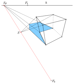
Parallel light actually always appears as sunlight. This is why the vanishing point of the parallel light rays that is necessary for the shadow construction is called the sun point . If the light comes from the front (as seen by the observer), the sun point is above the horizon . If the light comes from behind, the point of the sun is below the horizon. In the case of the parallel projection, the shadow of all essential vertical edges was determined again and again. In addition to the light beam through the upper point of an edge, the floor plan of this light beam was also drawn and then both straight lines were cut. This created the shadow point of the upper point and thus also the shadow of the vertical edge. With a central projection, every ray of light goes through the point of the sun. The outline of a ray of light is a horizontal straight line, the vanishing point of which is on the horizon. A vertical plane passes through the light beam and its floor plan and cuts the panel in a straight line. In the case of a vertical panel, this straight line is perpendicular to the horizon. In the case of an inclined image table, this straight line runs through the vanishing point of the z-direction.
Shadows when the picture is vertical
In this case, the vanishing point of all outlines of light rays lies perpendicularly below the sun point on the horizon. It is called the base of the sun . The actual shadow construction is technically like that in the case of a parallel projection with central light.
Shadows when the picture table is tilted
In inclined Blackboard vertical lines intersect are the panels and have an escape point in the example . The point of the sun (here it lies below the horizon, i.e. the light comes from behind) and the point of the sun base are in this case connected by a straight line . The construction of the shadow follows the scheme for vertical picture panels.
Shadows on the stand level with central light
If you have chosen a light source and its floor plan on the stand level or constructed it from a specification (in floor plan and elevation), the method for shadow construction in parallel projections (see above) can be adopted unchanged.
Another example
The last picture (warehouse with loading ramp and extension) is a central projection on a vertical panel and shows shadows on an inclined plane (roof of the extension) and on horizontal planes different from the stand level (ramp and stairs). In this case, too, with experience and practice, the shadow can be constructed in the perspective image (without the aid of the floor plan and elevation). Details: s. Weblink Descriptive Geometry for Architects, p. 172
See also
swell
- Fucke, Kirch, Nickel: Descriptive Geometry. Fachbuch-Verlag, Leipzig, 1998, ISBN 3-446-00778-4
- Cornelie Leopold: Geometric Basics of Architectural Representation. Verlag W. Kohlhammer, Stuttgart, 2005, ISBN 3-17-018489-X
- Adolf Göller: Textbook of shadow construction and lighting science , 2012 (orig .: 1895), Salzwasser-Verlag GmbH, ISBN 978-3-86444-807-2
Web links
- Descriptive geometry for architects (PDF; 1.5 MB). Script (Uni Darmstadt), pp. 20–22, 37, 104–110, 159–161, 172, 175


