Descriptive geometry
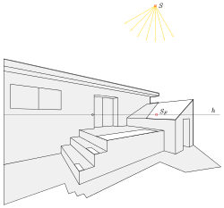
Representative geometry is the sub-area of geometry that deals with the geometrical-constructive processes of projections of three-dimensional objects onto a two-dimensional display plane. The areas of application of their methods are wide-ranging and, in addition to the best-known applications in technology and architecture, also extend to art, painting, maps and computer graphics. The descriptive geometry is not limited to the representation of spatial objects, but also offers possibilities to solve spatial geometric problems graphically: z. B. the determination of the intersection of a straight line with a plane or the intersection of two surfaces or the shadow of an object.
Screenshot from CATIA V5: machine part
In contrast to earlier times (see web link Gangolf Delabar ), descriptive geometry is no longer the only means to illustrate spatial objects or to solve spatial geometric problems. Today computers are used for this purpose (see web links and geometric modeling ). Today, the importance of descriptive geometry lies in training users of geometric software so that they understand what software can do and what inputs are required. For the first sketches of a (spatial) idea or interpretations and additions to computer drawings, drawing with a compass and ruler is an excellent exercise.
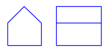
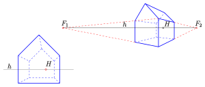
When displaying spatial objects in a drawing plane, two competing aspects play an essential role. If you want to achieve dimensional accuracy, this is usually only possible with a loss of clarity. For example, the following two pictures of a house allow easy conclusions about length, width and height; but they are not very clear. In contrast, the next two pictures bring out the spatial impression more. However, exact dimensions are difficult to read (especially from the picture on the right).
Imaging process
There are essentially two mapping methods used in descriptive geometry. Points and curves of an object are projected onto an image table (plane) with the help of rays (straight lines):
Parallel projection
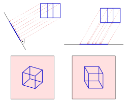
The imaging beams are parallel, e.g. B. in sunlight. A distinction is made between the two cases:
- The beams are perpendicular to the image board ( vertical parallel projection or orthogonal or normal projection).
- The rays are not perpendicular to the panel ( oblique or oblique parallel projection ).
Parallel projections are often used by engineers because of their partial ratio fidelity (partial ratios on straight lines remain invariant). The special case bird's eye view is an inclined parallel projection, which is used in particular to illustrate city maps. It is relatively easy to make by hand. Parallel projections can be created quickly as axonometric images or, in the case of larger objects, with the help of the incision process.
For almost all constructions in the descriptive geometry, the ground plan and elevation of an object are used. These are vertical parallel projections on a horizontal (floor plan) or vertical plane (elevation) (see two-panel projection ). With them, an object is clearly described spatially (with the corresponding designations).
Central projection
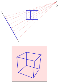
All imaging rays go through a point, the projection center or eye point . With parallel projection, the images of parallel straight lines are i. A. again in parallel. In the case of central projections, the images intersect parallel straight lines i. A. at one point, the vanishing point of the parallel tuft.
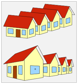
The images with a row of houses show that a central projection creates the best optical impression. In the image in parallel projection, the rear house appears larger than the first. This is due to an optical illusion. The eye recognizes the house as a spatial object and expects that a house of the same size, distant, is smaller, which is not the case with parallel projection.
Representation of real objects
In order to be able to represent objects such as houses, bridges, ... in a handy drawing plane or on a screen, the dimensions of the objects are usually suitably scaled (reduced) prior to projection, e.g. B. with factors 1/10, 1/50 or 1/100.
Tools
Technical aids
Classic aids for creating drawings are: paper as a flat drawing surface, pencil , compass , ruler , set square and curve ruler as a drawing device. Computers with suitable software (e.g. Cinderella , GeoGebra , Inkscape , Xfig , ...) can now replace all these tools. Such a graphics-capable computer is controlled manually with a computer mouse . If you want to have the result in front of you in black and white on paper, you use a computer-controlled printer . However, the classic aids (without computers) are still used today as a basis for the training of architects and engineers.
Theoretical tools
Basic statements from classical geometry are used as theoretical aids: theorems of rays , the theorems of Pythagoras and Thales , theorems about triangles , theorems about conic sections ( ellipses , ...), properties of quadrics ( sphere , cone , cylinder , ...).
Methods of Descriptive Geometry
Projections: two-panel projection, axonometry, architect arrangement, frontal perspective
The most important tools in descriptive geometry are floor plans and elevations and their assignments. They provide the spatial information for special representations and constructions. You learn the knowledge about it in
- Two-panel projection : Occasionally it is necessary to introduce further cracks. One then speaks of re-projections and multi-panel projections .
With the floor plan and elevation, you can then use
- Axonometry ,
- Incision process ,
- Orthogonal axonometry and
- Outline construction (for curved surfaces; see also channel surfaces )
Produce clear images of spatial objects in parallel projection.
Images in central projection are best constructed with the
- Architect's arrangement (similar to the incision method for parallel projections) and the
- Frontal perspective (perspective with one essential vanishing point, the main point).
In order to avoid parts of the image that appear distorted, you should first select the position of the image table, main point and eye point
draw in. Because only parts of the image within the visual circle appear undistorted in the perspective image.
Penetrations: intersections and intersection curves
An important basic task of descriptive geometry is the (graphic) determination of the intersection of a straight line and a plane. The procedure for this is called
- Puncture point method.
- ( Computational methods for determining an intersection point can be found here .)
Puncture points are z. B. needed at the
The basic tasks also include determining the
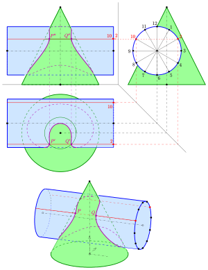
There are four standard methods for constructing points on the intersection curve of two surfaces (cylinder, cone, sphere, torus, surface of revolution):
- the auxiliary level method ,
- the surface line method ,
- the pendulum plane method and
- the auxiliary sphere method .
- ( Computational methods for determining an intersection curve can be found here .)
In the manufacture of models of penetrating cylinders and / or cones, coiled developments of these surfaces are often used. How to develop cylinders and cones is explained in
described.
Single panel projections: listed projection, roof layout
In addition to the two-panel and multi-panel projections, there are also special single panel projections . These are floor plans with additional information that spatially describe the objects. They are used in road construction
- Listed projection to
- Construct and represent slope surfaces.
The is concerned with the construction of ridge, valley and ridge lines (intersection lines) of flat roof surfaces
True length, true shape and reconstruction
Inclined stretches or flat figures in parallel projections are also rectified
- true length and true shape .
Analog methods for central projections (photos) are offered by the
Circle and sphere
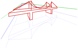
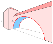
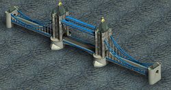
Circles and ellipses play an important role, especially as the boundary curves of objects such as cylinders, cones and surfaces of revolution (see pictures: tower with gate, bridge in frontal perspective). How to depict them with parallel projection and central projection and then draw them is shown in
described. Important aids are included
- Conjugate diameters of an ellipse and the
- Rytzsche axis construction , with which one reconstructs the main axes of an ellipse in order to finally relate the ellipse with the
- Draw vertex curvature circle method.
The representation of a sphere is very easy with perpendicular parallel projection. Its outline is a circle with the radius of the sphere. With all other essential types of projection, such as bird's eye view, cavalier's perspective and central projection, the outline of a sphere appears, apart from special cases, as an ellipse. How to construct the outline ellipse of a sphere is shown in
explained.
Helical lines
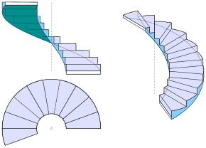
Helical lines play an essential role in architecture when depicting spiral staircases and in the technology of screws and twist drills. Their representation in plan and elevation, as well as orthogonal and oblique parallel projections is shown in
described.
Reflections
How to draw mirror images of objects that are created by reflection on water surfaces or wall mirrors in existing images (axonometries or central projections) is shown in
explained.
Special perspectives (views)
The basis for almost all representations and constructions in descriptive geometry are
- Floor plan and elevation : vertical parallel projections on a horizontal or vertical picture board.
The word perspective is often used in descriptive geometry to denote special descriptive views of a spatial object:
- The cavalier perspective or cabinet perspective is an oblique parallel projection (see axonometry ) on a vertical picture panel. All flat figures that are parallel to the picture panel are shown undistorted (see picture).
- The bird's eye or military perspective is
- in one case an oblique parallel projection (see axonometry ), the image table of which is horizontal, d. This means that all flat horizontal figures are shown undistorted (see picture) and
- in the other case, the bird's eye view is a central projection, the point of view of which is significantly higher than the greatest height of the object, and the image table is inclined.
- An engineer projection is an axonometric image with simple foreshortenings (0.5, 1, 1). The images of the x and y axes enclose angles of 132 ° and 97 ° with the image of the z axis (see axonometry ). Their advantages are: a) simple foreshortening, b) good image effect, c) (scaled) orthogonal projection, d) outlines of spheres are circles.
- An isometry is an axonometric image in which the distortions in the x, y, and z directions are all the same. The following also applies to standard isometry: The images of the coordinate axes intersect at an angle of 120 °. A typical property is: In the projection of an axially parallel cube, two points coincide.
- The frog's eye view is a central projection, the eye point of which is close to the standing plane (see picture).
- Central perspective is a central projection.
- Perspective is often used as a short form for central perspective .
- Frontal perspective is a central projection of an object with three essentially mutually orthogonal directions (e.g. cuboid, house), two of these directions running parallel to the picture board and thus their vanishing points are at "infinity". Such a view is also called a perspective with a vanishing point (see picture). The one particular vanishing point is usually the main point. The advantage of a frontal perspective: All flat figures in planes parallel to the picture panel are only scaled, but not distorted (see examples: bridge and house in frontal perspective).
- Perspective with two vanishing points is a central projection in which the vanishing points to two mutually perpendicular orthogonal directions (mostly horizontal) play an essential role (see picture).
- Perspective with three vanishing points is a central projection in which three vanishing points play an essential role. Here the panel is inclined (see house in bird's eye view of the central projection).
- Parallel perspective is a parallel projection.
- Polar perspective is an earlier term for central projection (see web link Gangolf Delabar ).
education
Descriptive geometry is now a subject in technical - vocational schools and a fundamental subject in the training of engineers at a technical university or college .
The topic is the recording and representation of spatial , especially technical structures (geometric bodies , buildings , representation of the terrain , etc.).
The most important aids are construction drawings , perspective (central projection ), axonometry , quoted projection and the like. In addition to learning drawing techniques, spatial imagination and expression should be promoted and links to mathematics , technology and the visual arts should be established.
A purely graphic subject (applied geometric drawing ) until the 2000s , today it is widely used in computer graphics . In the last few years the importance of the subject had not decreased in general, but in training, because the computer-aided construction (CAD) requires different skills than the drawing by hand. Since schools have also been well equipped with computers in the classroom, the subject has once again become one of the most important basic technical training courses and also includes learning the associated programs - generally market-leading special CAD applications in the industry.
The actual thought work, the conversion of the 2D representation (whether paper or screen) into a 3D (thought) model is retained by the engineer or designer even when using CAD. On the other hand, it becomes more difficult to identify spatial construction problems (e.g. connection profiles with inclined cuts) if (and because) one relies on the software.
“Descriptive geometry is not a prerequisite in a superficial sense in order to master a CAD program. Practicing them is rather a primary experience in that spatial imagination, the assessment and selection of solution strategies and the precision of thinking are trained. "
On the history of descriptive geometry

Plans with specific specifications play an important role in the systematic construction of structures. Floor plans and elevations were already used in ancient times . The oldest written evidence of this is the work Ten Books on Architecture by the Roman builder Vitruvius . But it was not until Albrecht Dürer (1471–1528) wrote the first real textbook of descriptive geometry in the early modern period: Underweysung with the circle and Richtscheydt (Nuremberg 1525). On pages 34–37 of the first book the conic sections ellipse, parabola and hyperbola appear. Gaspard Monge (1746–1818) introduced the strict allocation of ground plan and elevation for the first time in his book Geometrie descriptive in order to solve spatial problems graphically. The basic tasks of descriptive geometry can already be found there in the version that is still used today.
The basics of central projection were already known to the Greeks and Romans. But it was not until the Renaissance that this type of representation of spatial conditions was rediscovered through painting and further developed to blossom. See De pictura by Leon Battista Alberti (1404). The masters of this time were Albrecht Dürer (1471–1528), Leonardo da Vinci (1452–1519) and Michelangelo (1475–1564).
literature
The first German-language textbook on descriptive geometry comes from Albrecht Dürer (1525). After the textbook by G. Monge (1798), many other books were written in German from 1800. In order to give interested parties a quick overview of current literature, newer books are listed here first.
Published after 1950 :
- H. Brauner : Textbook of constructive geometry. Springer-Verlag, Vienna / New York 1986, ISBN 3-211-81833-2 .
- H. Brauner, W. Kickinger: Baugeometrie I, II. Bauverlag, Wiesbaden / Berlin 1977, 1982, ISBN 3-7625-0825-9 , ISBN 3-7625-2690-7 .
- R. Fucke, K. Kirch, H. Nickel: Descriptive Geometry. Fachbuch-Verlag, Leipzig 1998, ISBN 3-446-00778-4 .
- O. Giering, H. Seybold: Constructive engineering geometry. C. Hanser Verlag, Munich / Vienna 1979, 1987, ISBN 3-446-14842-6 .
- U. Graf , M. Barner : Descriptive Geometry. Quelle & Meyer, Heidelberg 1961, ISBN 3-494-00488-9 .
- F. Hohenberg : Constructive geometry in technology. Springer-Verlag, Vienna 1966, ISBN 3-211-80763-2 .
- J. Hoschek, G. Spreitzer: Tasks for descriptive geometry. BI-Verlag, 1974, ISBN 3-411-01451-2 .
- C. Leopold: Geometric Basics of Architectural Representation. Verlag W. Kohlhammer, Stuttgart 2005, ISBN 3-17-018489-X .
- E. Müller, E. Kruppa : Textbook of the performing Geomelrie , Springer-Verlag, Vienna, 1961, ISBN 978-3-211-80589-3 .
- A. Pumann: Descriptive Geometry. Part 1 and Part 2, Pumann, Coburg 1998, ISBN 3-9800531-0-5 , ISBN 3-9800531-1-3 .
- F. Rehbock : Descriptive Geometry. Springer-Verlag, Berlin / Göttingen / Heidelberg 1969, ISBN 3-540-04557-0 .
- F. Rehbock: Geometric perspective. Springer-Verlag, Berlin / Heidelberg / New York 1980, ISBN 3-642-67542-5 .
- F. Reutter: Descriptive Geometry. I and II, Verlag G. Braun, Karlsruhe 1979, ISBN 3-7650-1201-7 , ISBN 3-7650-2021-4 .
- R. Stark: Descriptive Geometry. Schöningh-Verlag, 1978, ISBN 3-506-37443-5 .
- K. Strubecker : Lectures in descriptive geometry. Vandenhoeck & Ruprecht, Göttingen 1967 ( online copy ).
- R. Thomae : perspective and axonometry. Springer-Verlag, 2013, ISBN 978-3-322-95328-5 .
- K. Ulshöfer, D. Tilp: Descriptive geometry in systematic examples. Worksheets. Buchner, 2015, ISBN 978-3-7661-6092-8 .
- W. Wunderlich : Descriptive Geometry I (= university pocket book. 96 / 96a ). Bibliographer. Inst., Mannheim 1966.
- W. Wunderlich: Descriptive Geometry II (= university pocket booklet 133 / 133a ). Bibliographer. Inst., Mannheim 1967.
- U. Kurz, H. Wittel: Böttcher / Forberg technical drawing. Springer-Vieweg, Wiesbaden 2014, ISBN 978-3-8348-1806-5 .
- J. Hoschek, D. Lasser: Fundamentals of geometric data processing. Teubner-Verlag, Stuttgart 1989, ISBN 3-519-02962-6 .
Published before 1950 :
- J. Adhemar: Descriptive Geometry , Jent and Gassmann Verlag, Solothurn, 1845.
- PB Fischer: Descriptive Geometry. Springer Fachmedien, Wiesbaden, 1921, ISBN 978-3-663-15478-5 .
- JT Hjelmslev : Descriptive Geometry , Leipzig, Berlin: BG Teubner, 1914, ISBN 587635130X .
- G. Loria : Lectures on Descriptive Geometry. 2 volumes. BG Teubner, Leipzig 1907.
-
E. Müller : Textbook of descriptive geometry for technical universities.
- First volume. BG Teubner, Leipzig / Berlin 1908.
- Second volume. 2nd Edition. BG Teubner, Leipzig / Berlin 1920.
- E. Müller: Lectures on descriptive geometry. 3 volumes. Franz Deuticke, Leipzig / Vienna 1923 1931.
- R. Müller : Guide for lectures on descriptive geometry at the Ducal Technical University of Braunschweig. F. Vieweg, Braunschweig 1899.
- E. Papperitz : Darstellende Geometrie , in Encyklopädie der Mathematischen Wissenschaften including their applications , Leipzig, BG Teubner-Verlag, 1907, 3rd volume, pp. 517-594. Göttingen Digi Center
- K. Pohlke : Ten tables on descriptive geometry. Gaertner-Verlag, Berlin 1876 (Google Books.)
- K. Rohn , E. Papperitz: Textbook of the descriptive geometry. 2 volumes. Leipzig 1893, 1896.
- G. Schaffnit: Geometrical construction theory or descriptive geometry: (Géométrie descriptive) , Heyer-Verlag, Darmstadt, 1828.
- G. Schreiber : Special descriptive geometry: for architects, technicians, mechanics and building craftsmen, especially for building, ploytechnical and higher trade schools , O. Spamer Verlag, Leipzig, 1865.
- G. Scheffers : Textbook of the descriptive geometry. J. Springer, 1922.
- EL Stiefel : Textbook of Descriptive Geometry. Springer-Verlag, Basel 1947, ISBN 978-3-0348-4098-9 .
- C. Wiener : Textbook of descriptive geometry. 2 volumes. Teubner, Leipzig 1884, 1887, online at archiv.org: Volume 1 , Volume 2.
Web links
- Descriptive geometry for architects. (PDF; 1.5 MB). Script (Uni Darmstadt).
- Descriptive geometry for civil engineers. (PDF; 1.2 MB). Script (Uni Darmstadt).
- Fundamentals and elements of traffic engineering. ( Memento from August 10, 2013 in the Internet Archive ). (PDF; 493 kB). TU Dresden.
- Descriptive geometry. Script (University of Stuttgart).
- Teacher training at the Vienna University of Technology
- List 1 , List 2 of the questions in oral exams.
- Descriptive Geometry , (PDF; 4.26 MB), TU Vienna
- Gangolf Delabar: The polar and parallel perspective . 1893.
- COMPUTER-aided descriptive and constructive geometry. Darmstadt University (PDF; 3.4 MB).
- Geometry and Algorithms for COMPUTER AIDED DESIGN.
- Clear Flash tutorials for perspective drawing and viewing.
- Exercises with solutions in 2-board projection (English).
- Descriptive geometry. ( Memento of December 8, 2015 in the Internet Archive ). University of Magdeburg.
- Strubecker: Lectures on descriptive geometry. TH Karlsruhe.
- G. Monge: Descriptive Geometry. Full text of the German edition from 1900.
- H. Stachel : The history of descriptive geometry in Austria
Individual evidence
- ↑ PDF at: igpm.rwth-aachen.de.
- ↑ Wikisource: Underweysung with the circle and Richtscheydt.
- ↑ Geometry descriptive.


