
Ellipse (Descriptive Geometry)

Circles and ellipses play an important role in descriptive geometry mainly as boundary curves of objects such as cylinders, cones and surfaces of revolution. If you cut off a straight circular cylinder or a straight circular cone at an angle, the intersection curve for the cylinder is always an ellipse, for the cone only if the cut is not too inclined. There is then the need to project a circle or an ellipse either by means of a parallel projection or a central projection onto an image board.
- A parallel projection always creates an ellipse as an image if the plane of the ellipse is not parallel to the direction of projection (see below).
- A central projection creates an ellipse or a parabola or a hyperbola if the plane of the ellipse does not contain the eye point (projection center) (see below).
Since the hyperbola and parabolic cases are rather rare and the circular or elliptical case is the rule, effective methods were developed for ellipses to construct their images with parallel and central projection. It is relatively easy to draw an ellipse if you know its center and four vertices. So you try to determine this. In the case of a parallel projection, this is significantly easier than in the case of a central projection, since in a parallel projection the image of the center is the center of the image ellipse (see below). Parting, however, almost never merges into parting again. In the case of parallel projection, vertices provide at least so-called conjugate diameters of the image ellipse, from which the vertices can be reconstructed with the help of the Rytz construction . Since there is usually no ellipse available, it is best to draw an ellipse approximately freehand with the help of its four logs' curvature circles (see below). This method produces astonishingly "beautiful" ellipses. Computer drawing programs also often offer the possibility of drawing ellipses at known center points and semiaxis.
Parallel projection of an ellipse
The proof that the image of an ellipse is again an ellipse in a parallel projection can be done conceptually (without calculation). This is described in many descriptive geometry books. A shorter way uses analytic geometry and is shown here.
Description of an ellipse


An ellipse can be understood as an affine image of the unit circle and with a parametric representation

describe: An affine mapping consists of a linear mapping and a subsequent shift. The vector describes the center of the ellipse and the pairs of points as well as describes the diameter of the ellipse and are the images of two orthogonal diameters of the unit circle. Such pairs of diameters are called conjugate diameters . stand i. A. not perpendicular to each other. That is, and are i. A. not the vertex of the ellipse. Differentiation is used to convince yourself that


- (T): the tangents in the points have the direction of and the tangents in the points have the direction of (see picture).


Since in an affine mapping the center points of lines merge into the center points of the image lines and parallelism is retained, the following applies:
- (M): The midpoints of the parallel chords lie on the diameter and vice versa. (see picture)
Since a circle has any number of pairs of orthogonal diameters, an ellipse has any number of pairs of conjugate diameters. A pair of points describes a diameter and the pair describes the conjugate diameter.


The property (M) makes it possible to construct a diameter of the ellipse as a point set (curve) from two parallel chords for a given ellipse. The center of the diameter is the center of the ellipse. If you then construct the center of a chord that is too parallel, you get by connecting the center of the chord with the diameter to be conjugated .


The following property is important for the projection of an ellipse:
- If the vectors are out of space , a parametric representation of an ellipse in space is obtained.

Description of a parallel projection


A parallel projection projects points (in space) onto a plane (image table) with parallel rays. If the direction of projection and the image plane is described by the equation , then a point is on


shown (see parallel projection ). It must apply, otherwise the image panel is projecting , i.e. H. would be parallel to the direction of projection.

If you choose the image table so that it contains the zero point of the coordinate system and choose the length of the normal vector so that is, the projection formula takes the following simple form:


In this form, the projection is a linear image .
If so, there is an orthogonal projection (onto the plane).

Image of an ellipse
If you form an ellipse

according to the simplified projection formal, the curve is the image

where is. So if the elliptical plane is not parallel to the direction of projection:

- The image of an ellipse is an ellipse when projected in parallel. In this case , the plane of the ellipse and the image table are parallel and the image is congruent to the original ellipse .
- The image of the center it is the center of the image ellipse.
- Conjugated radii (diameter) change into the same.

Construction of the picture ellipse
Construction steps:
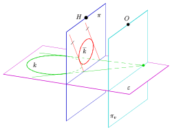
- Construction of the center and two conjugate points of the image ellipse. As a rule, one chooses a vertex and a secondary vertex of the original ellipse as archetypes of .
- Determination of the elliptical axes with the help of the Rytz construction (see picture).
- Rotation of 90 degrees open to.
- Draw the auxiliary line through the rotated point .
- Circle whose center is the center of the rotated point and .
- The circle intersects the auxiliary line in two points, the connections of which result in the straight axis.
- The half-axis lengths can be measured on the auxiliary straight line and the four vertices can be drawn with them.
- Draw the ellipse with a compass or the vertex curvature circle method . In doing so, you first determine (if the center point and the four vertices are known) according to the method described in the picture, the centers of two vertex curvature circles (the auxiliary point complements the points to form a rectangle). With the help of the radii of these circles, the two missing center points for the remaining two vertex circles of curvature can be plotted and the circles of curvature drawn. Now it is relatively easy to draw a curve freehand or with a curve ruler in such a way that it touches the large circles of curvature from the inside and the small ones from the outside.


special cases
- If the image table is parallel to the plane of the circle or ellipse (e.g. bird's eye view, see picture), the circle or ellipse is shown undistorted. So only the image of the center point and, in the case of an ellipse, two vertices need to be determined.
- In the case of an orthogonal parallel projection of a circle , no Rytz construction is usually necessary (see orthogonal axonometry ), since the circle diameter, which is parallel to the image table, is mapped onto the main axis of the image ellipse. With the help of a further point on the ellipse, the small semiaxis can then also be determined.
Central projection

A central projection is much more difficult to handle mathematically and graphically. In contrast to parallel projection, the image of a circle can not only be an ellipse, but also a hyperbola and, in special cases, a parabola. Even in the case that the picture is an ellipse, the center of the circle does not merge into the center of the picture ellipse (see picture). This means that perpendicular circular diameters do not change into conjugate diameters of the image ellipse. The drawing instruments of parallel projection cannot be used directly. Only when one is able to determine the center point of an image ellipse and a pair of conjugate diameters (radiuses) can one determine the axes with the Rytz construction as above and draw the image ellipse.
If you are only interested in a sketchy drawing of the image ellipse, you can depict a tangent parallelogram including points of contact and insert the ellipse with the help of a curve ruler (see example: cube with circles). The accuracy can be increased by adding further points, e.g. B. the points on the diagonals and their images, increase.
If the image of a circle is a hyperbola , it is worthwhile to construct the asymptotes of the image hyperbola . They are the images of the tangents at the two points of intersection of the circle with the plane of disappearance. The intersection of the asymptotes is the center of the image hyperbola. It is then sufficient to construct a point on the hyperbola from the ground plan and elevation. With the property “Center of the chord also halves the chord of the asymptotes” , any number of hyperbolic points can then be generated in the perspective image.
Possible images of a circle

If the circular plane passes through the eye point, i.e. H. is projecting, the image of the circle is a segment or straight line.
In all of the following cases, the circle should not lie in a plane through the eye point.
- Case 0: If the circle is parallel to the image table , the image is a circle again and the center of the circle merges into the center of the image circle. If the circle is in the table, the radius remains unchanged; if it is not in the image table, the radius of the image circle is scaled (see image).
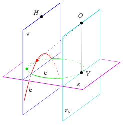
- Case 1: If the circle lies in front of the vanishing plane (i.e. the plane through the eye point, which is parallel to the image table, see picture), the picture is an ellipse (see picture).
- Case 2: If the circle touches the vanishing plane (at a point), the image is a parabola .
- Case 3: If the circle intersects the vanishing plane (in two points), the image is a hyperbola .

To see this, imagine the cone created by the circle and the eye point. This is i. A. not a straight circular cone, but the affine image of one. The following also applies to such a cone (as with a straight circular cone): Plane sections with planes that do not contain the apex of the cone are non-degenerate conic sections . Namely a) an ellipse (case 0, 1), if the plane is not parallel to a surface line and only intersects the cone in one curve, b) a parabola (case 2), if the plane is parallel to a surface line and c ) a hyperbola (case 3) when the plane intersects the cone in two curves. In the last two cases in particular, the circle cannot be mapped completely, only a part. In the case of a hyperbola, only the arc of a circle in front of the plane of disappearance is mapped, just as in a central projection only points in front of the plane of disappearance, i.e. H. points on the side of the illustration. If one mentions that a central projection mimics seeing with one eye, one must not imagine the picture board as a retina, but that viewing a central projection (with the eye in the eye point and fixation of the main point) completely replaces the real object.
When projecting a sphere with circles of longitude and latitude, all cases can occur if the eye point (projection center) lies in the sphere (see picture).

Central projection of a circle parallel to the picture board

Central projection of a circle as an ellipse


Central projection of a circle as a parabola
Central projection of a circle as a hyperbola


Projection of a circle as an ellipse
So that the image of a circle becomes an ellipse, the circle must lie in front of the disappearance plane (see image). This is assumed in the following.
In order to be able to construct an ellipse, two conjugate diameters are required. Two conjugate diameters intersect at the center. A diameter of an ellipse always has parallel tangents in the ellipse points (see above). So you need a criterion when two straight lines are mapped onto two parallel straight lines. The criterion is:
- Straight lines that intersect on the vanishing plane are mapped onto parallel straight lines (see picture).

Central projection of two straight lines as parallel straight lines
Central projection of a circle as an ellipse with tangents


Projection of a horizontal circle

In practice, one chooses with the central projection of a circle (before Verschwindungsebene) the tangent pair in the nadir point of the solder (see Fig.) Intersects the center of the circle to the Verschwindungsgerade the county level. The line is the archetype of the first diameter of the picture ellipse. Since it is parallel to the vanishing line and thus also to the image table, the archetype of the conjugate diameter lies on the perpendicular line (see image: points ) and the associated tangents are parallel to the image table. This means that the archetypes of the second parallel pair of tangents (the image ellipse) are already parallel in the archetype. The point of intersection of the circular chords is the archetype of the center of the image ellipse. Since you only need the center point and two conjugate radiuses for the Rytz construction, it is sufficient to map two conjugate points (in the picture ). With the help of the Rytz construction (see above) one determines the four vertices and finally draws the ellipse with the help of the curvature circle method.


Central projection of a circle as an ellipse: construction template in architect arrangement

Central projection of a circle as an ellipse: solution


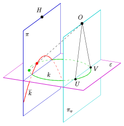
Projection of a vertical circle

When projecting a vertical circle (not parallel to the image table), one rotates the circle around the horizontal line through the center point so that it is horizontal (see example). It should be noted that the vanishing line of the circular plane (the light blue line in the picture) is also rotated. In this position, as in the previous example, the archetypes of the center and two conjugate points of the image ellipse are determined and they are rotated back again (in plan and elevation). The points are transferred to the perspective image and the ellipse axes are determined there with the help of a Rytz construction. Then the ellipse can be drawn. If you want to use the circle as the basis for a clock face (see picture), you first enter the subdivisions in the floor plan on the horizontal circle and turn the points with the circle back into the vertical position. Then the points are transferred to the perspective image.

A further example for the central projection of a vertical circle shows the first image (see above.): Tower with an archway.
Special case: stereographic projection

The network of arcs within the purple circle (left) is called Wulff's network . It was previously used in crystallography to create a stereographic projection by hand.
In stereographic projection , points on the spherical surface are projected from one point on the sphere onto the tangential plane of the opposite point. If you choose an image plane parallel to it, a stereographic projection is created that is scaled to the standard image. So that the picture does not get too big, you can also project onto the plane parallel to the tangential plane through the center of the sphere (see picture). The great circle cut out by the image plane is already in the image plane. He is thus mapped onto himself (see purple circle). What is special about a stereographic projection is its fidelity to the circle , i. H.:
- The image of every circle that does not go through is again a circle (!). A circle through the projection center is mapped onto a straight line (in the picture: blue and green).

So circles are mapped onto circles even though they are not parallel to the picture board (see section Possible pictures of a circle ).
A proof of the true-to-circle of the stereographic projection can be found here .
Construction of elliptical tangents and their points of contact
Constructions of elliptical tangents are usually carried out in three steps:
- Step 1
- Transformation of the ellipse and possibly additional given points and straight lines by means of an affine axis extension so that the ellipse merges into one of the two vertex circles.
- 2nd step
- Solving the tangent problem on the vertex circle.
- 3rd step
- Reverse transformation of the circle tangents and points of contact.
The tangents themselves are often easy to draw freehand. But the points of contact can only be estimated very imprecisely freehand and should be constructed using the methods described here.
Tangents and their points of contact can also be determined computationally within the framework of analytical geometry . See also ellipse .
Circle tangents
- Tangent in a circle point
If a circle and a circle point (blue in the drawing) are given, the perpendicular line to the radius is the tangent (red) in the point .


- Tangents through a point outside the circle
If there is a circle and a point that is not on top of the line , the two points of contact of the desired tangents are on the Thales circle (green in the drawing) above the line . The tangents at the point are the straight lines .


- Tangents parallel to a given line
Are a circle and a straight line given, the contact points of the tangents are the intersections of the Perpendicular to through the center . The tangents passing through or and parallel to .


Tangent in a circle point

Tangents through a point outside

Tangents parallel to a straight line


Axis stretching

If a straight line (the axis) and a pair of points are not given up, the mapping rule in the drawing describes a perspective- related mapping with the axis and direction . If the straight line is not parallel to the axis, the affine mapping is called an axis extension . (If is parallel to the axis , the figure is a shear .) The axis consists of the fixed points of the figure. If the straight line is parallel to , the point of intersection of the parallel through to with the parallel through to the straight line .


When constructing tangents to an ellipse, the major axis of the ellipse is selected as the axis and the minor axis of the ellipse indicates the direction of the axis extension. The minor vertices are mapped to the points of the large vertex circle on the minor axis (see next picture). The ellipse is thus mapped (stretched) to the large apex circle by the axis extension. Point and image point always lie on a perpendicular to the main axis.
If it is more convenient to draw, the ellipse can also be depicted (compressed) on the small apex circle.
Elliptical tangents
In this section it is always assumed that the ellipse is known by its 4 vertices. If only conjugated radiuses are known, the vertices must first be determined with the help of a Rytz axis construction and then the ellipse must be drawn using one of the available methods. For the relationship between vertex circle points and ellipse points, knowledge of the point construction according to de La Hire is helpful.

- Tangent at an ellipse point
Given an ellipse and a point of the ellipse. The ellipse is mapped to the large vertex circle with the help of the extension on the main axis, which maps the vertex to the point of the large vertex circle . The point changes into the circle point . Then (as described above) you construct the circle tangent in . If the tangent is parallel to the major axis, one of the minor vertices is and the tangent is parallel to the major axis. In the other case, the circle tangent intersects the main axis of the ellipse at a point . During the reverse transformation, it changes back to and the point is a fixed point as an axis point. So the tangent is the straight line .


If the point cannot be reached in the drawing (outside the drawing area), the other axis of the ellipse should be selected as the extension axis and the ellipse should be compressed onto the small apex.
Another simple construction of the tangent at an elliptical point uses the focal point property . However, focal points are only rarely used in descriptive geometry and must first be constructed.

- Tangents through a point outside
Given an ellipse and a point outside the ellipse. The ellipse is mapped to the large vertex circle with the help of the extension on the main axis, which maps the vertex to the point of the large vertex circle . The point changes into the point . The straight line and its image below the axis extension are used to construct. Then you construct the circle tangents (as described above) using the Thales circle. The two points of contact on the apex circle become the points of contact of the desired tangents by reversing the axis extension. The elliptical tangents through P are the straight lines .


If the point lies on one of the ellipse axes, this axis can be selected as the extension axis. is then a fixed point and the construction is simplified.

- Tangents parallel to a straight line
Consider an ellipse and a straight line that is not parallel to an axis of the ellipse. (Otherwise the desired tangents are vertex tangents.) The ellipse is mapped onto the large vertex circle with the help of the extension on the main axis, which maps the vertex to the point of the large vertex circle . Since you any for the solution of the problem parallels the line can use one chooses here to parallel line through . (This optically rectifies the construction.) With the help of the fixed point one obtains . The tangents of the large vertex circle that are parallel to each other provide their points of contact on the circle. The reverse transformation of these points results in the contact points of the elliptical rods. (In the drawing, only the point and the tangent were constructed at this point.)


example
The drawing shows a truncated cylinder (obliquely cut vertical circular cylinder) in a bird's eye view . The base circle is again a circle with the same radius. The construction of the cut ellipse was carried out by applying conjugate radiuses and subsequent Rytz construction, but was omitted here for a better overview. The axes and vertices of the cut ellipse are already known. In order to find the parallel contour lines, the tangents parallel to the cylinder axis and their contact points are constructed (see above). Note that the contact points are point-symmetrical to the center of the ellipse. So only one point of contact has to be laboriously constructed. The contact points on the base circle lie on the diameter perpendicular to the cylinder axis.
Actually, the ellipse tangents are already known from the circle tangents. In order to determine the contact points (end points of the contour lines), the complex construction must then be carried out.
See also
literature
- Fucke, Kirch, Nickel: Descriptive Geometry. Fachbuch-Verlag, Leipzig 1998, ISBN 3-446-00778-4 , p. 57.
- Graf, Barner: Descriptive Geometry. Quelle & Meyer, Heidelberg 1961, ISBN 3-494-00488-9 , pp. 104, 272.
- C. Leopold: Geometric Basics of Architectural Representation. Verlag W. Kohlhammer, Stuttgart 2005, ISBN 3-17-018489-X , p. 55.
Individual evidence
- ^ Graf, Barner: Descriptive Geometry. Quelle & Meyer, Heidelberg 1961, ISBN 3-494-00488-9 , p. 277.
- ↑ R. Fucke, K. Kirch, H. Nickel: Descriptive Geometry. Fachbuch-Verlag, Leipzig 1998, ISBN 3-446-00778-4 , p. 60
- ^ R. Stark: Darstellende Geometrie , Schöningh-Verlag, 1978, ISBN 3-506-37443-5 , p. 74
Web links
- Descriptive geometry for architects (PDF; 1.5 MB). Script (Uni Darmstadt), pp. 58, 138.