Roof design
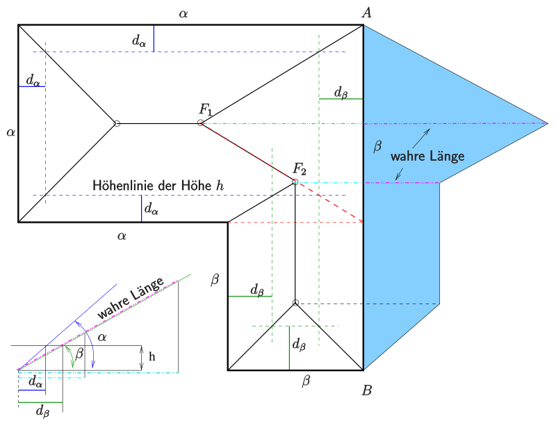
In construction, roof design is understood as the spatial-geometric determination of the position of the cut edges, i.e. the ridges , ridges and valleys , which result from the merging of several roof surfaces . An essential point here is the determination of the true length of the ridges and grooves, since these appear shortened as three-dimensional, inclined structures in the two-dimensional plan view .
The various approaches to centering out a roof and the resulting finished roof design result from the geometry of the floor plan, the height or the heights of the eaves and the roof slopes.
If all roof surfaces of a roof have the same roof inclination, it is irrelevant for the roof layout, since all roof intersection lines run either in the bisector or parallel to the corresponding eaves.
However, different eaves heights and roof slopes require a previous drawing or calculation of one or more contour lines.
In books on descriptive geometry , roof outlines and slope areas are covered under the heading of listed projections .
Implementation of the roof design
- Choose the height of a level so that the contour lines in the floor plan are at least 1–2 cm away from the eaves edge. With the same roof pitch , contour lines have the same distance from the eaves everywhere.
- Draw the contour lines for each roof level in the floor plan.
- Cut the contour lines of neighboring roof surfaces and connect the points of intersection with the corresponding corners of the eaves polygon. This gives the ridge and valley lines . With the same roof pitch , ridge and valley lines are bisectors of the associated eaves!
- The intersection of corresponding ridge or valley lines results in points of ridge lines .
- Missing ridge lines are obtained by cutting the corresponding (not adjacent) roof levels (with the help of the contour lines).
- The true shape of a certain roof surface is obtained by rotating the plane around the eaves edge into the plane of the drawing. The true distance of a point from the eaves edge results as the hypotenuse of the associated supporting triangle.
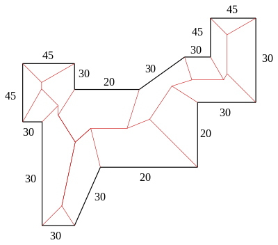
Another example : In the much more complex example (see figure), you have to think of individual parts of the eaves edge polygon as detached and, for the then simplified case, determine ridge and valley lines using the method described above. These are then cut by the existing lines. For example, detach the extension in the upper left corner and determine the ridge lines of the then simple extension roof (the eaves polygon is a rectangle). The rest of the roof area is also simplified by removing the extension.
See also
swell
- Fucke, Kirch, Nickel: Descriptive Geometry. Fachbuch-Verlag, Leipzig, 1998, ISBN 3-446-00778-4 , p. 133.
- Cornelie Leopold: Geometrical Basics of Architectural Representation , Verlag W. Kohlhammer, Stuttgart, 2005, ISBN 3-17-018489-X , p. 195
Web links
- http://www.geometrie.tuwien.ac.at/asperl/projekt/dach1.htm (TU Vienna)
- Descriptive geometry for architects (PDF; 1.5 MB). Script (Uni Darmstadt)
- Development of the roof design


