Pendulum plane method
The pendulum plane method is a method of descriptive geometry to determine points of the intersection curve of two cones or a cone with a cylinder graphically in plan and elevation . Sections of the cylinders / cones with planes that cut straight lines from these surfaces are considered . In the case of a cone, this is only the case if a plane passes through the apex of the cone. In the case of a cylinder, the plane must be parallel to the cylinder axis.
- If you want to cut two cones , the auxiliary planes must go through the two cone tips.
- If you want to cut a cone with a cylinder , the auxiliary planes must contain the apex of the cone and be parallel to the cylinder axis.
In both cases, the auxiliary planes have a straight line in common; they oscillate around this straight line during construction.
The common auxiliary plane method uses plane cuts with parallel planes. However, it also allows circles as flat cuts. This means that it can also be used with other surfaces ( sphere , torus ). If possible, the usual auxiliary plane method is used. However, there are cases that can be handled with the auxiliary plane method but not with the pendulum plane method.
Comment:
- The simpler auxiliary plane method can always be used to cut two cylinders.
- Another method of drawing intersection curves is the auxiliary sphere method . It uses balls as auxiliary surfaces and is particularly suitable for cutting surfaces of revolution whose axes of rotation intersect.
- Computational methods for determining points on an intersection curve are explained in the article Intersection curve .
- The pendulum plane method is also available for the intersection of two pyramids or a pyramid with a prism (see Fucke, Kirch, Nickel: p. 84).
Explanation of the procedure using an example
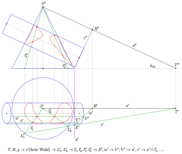
As an example, a straight circular cone is to be cut with a circular cylinder whose axis is inclined (see picture). The axes of the cone and cylinder do not intersect. If the axes intersected, the simpler auxiliary sphere method could be used. If the cylinder axis were not inclined (i.e. horizontal), the auxiliary plane method would be applicable. So only the pendulum plane method comes into question for the given situation.
Idea of the process: So that planes cut straight lines from both surfaces, the planes must pass through the apex of the cone and run parallel to the cylinder axis, i.e. H.
- all pendulum planes must contain the parallel to the cylinder axis through .
For a specifically selected pendulum level ,
- their intersection can be determined with the base circle of the cone. This provides the line of intersection with the cone.
- their intersection with a bottom circle of the cylinder (here the right circle) can be determined. This provides the line of intersection with the cylinder.
- If the sections are not empty, points on the section curve are obtained.
The implementation takes place this idea in a two-panel projection (crack edge ):
- The parallel to the cylinder axis through the cone tip is drawn in plan and elevation. The plan is parallel to the edge of the crack, the elevation meets the plan board at the point (trace point ).
- is the plane through the (right) base circle of the cylinder. Since the second is projecting (i.e. perpendicular to the elevation board), its elevation appears as a straight line. The intersection of with the plan table (plane containing the base circle of the cone) is the straight line .
- Now a pendulum level is determined by a (suitable) choice of its ground plan track . Suitable means that the plane will intersect both surfaces if possible. A minimum requirement is that the base circle of the cone must intersect (in the picture in the points ). The straight lines are the straight lines of intersection of the pendulum plane with the cone.
- The pendulum plane intersects the plane at points and . So its connecting line is the intersection of the pendulum plane with the base circle plane of the cylinder and the intersection of with the cylinder circle provides points of intersection . Parallels to the cylinder axis through are the straight lines of intersection of the pendulum plane with the cylinder.
- The (not empty) sections initially provide points of the intersection curve between cone and cylinder in the floor plan, which are then transferred to the elevation using folders.
- If enough points are constructed in this way, intersection curves can be drawn with a curve ruler (in this case two).
literature
- Fucke, Kirch, Nickel: Descriptive Geometry. Fachbuch-Verlag, Leipzig 1998, ISBN 3-446-00778-4 , p. 90
- Graf, Barner: Descriptive Geometry. Quelle & Meyer, Heidelberg 1961, ISBN 3-494-00488-9 . P. 239
- Leopold, C .: Geometric basics of architectural representation. Verlag W. Kohlhammer, Stuttgart 2005, ISBN 3-17-018489-X . P. 154


