Outline construction
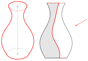
In descriptive geometry , the outline of these surfaces is used to represent curved surfaces (spheres, cylinders, surfaces of revolution, ...) . Under the outline one can imagine surface curves that separate the surface from its surroundings for a viewer (see left picture with the vase). Obviously, the outline of a surface depends on the type of projection (view). For smooth surfaces (there is a tangential plane at every point), the following applies: In an outline point of a surface, the projection ray is a tangent to the surface. With parallel projection the direction of projection is the same at every point, with central projection (the rays go through a fixed point, the eye point) the direction of projection depends on the point to be projected. The totality of all outline points forms the outline curve (or outline) of the surface. For example, the contour curve of a sphere in parallel projection is a great circle (the center of the circle is also the center of the sphere). In the case of central projection, the outline is also a circle of the sphere, but its center is not the center of the sphere (see picture). In descriptive geometry, the contour curve on the surface is called the true contour . The projection of the true outline is a flat curve (in the illustration) and is called the apparent outline . With a parallel projection, the true outline of a sphere is always a great circle. With perpendicular parallel projection, the apparent outline is a circle congruent to the true outline (the radii are the same). With a bird's eye view (oblique parallel projection, see picture) the apparent outline is an ellipse . In the case of central projection, the true outline is in any case also a circle (provided the eye point is outside the sphere). The projection of this circle, i.e. the apparent outline, can again be a circle, but only if the center of the sphere is on the perpendicular from the eye point to the image board (see picture). In all other cases the apparent outline of a sphere is an ellipse when projected from the center. The further away the center of the sphere is from the plumb line, the more distorted the apparent outline.
As the example with the vase shows, not only points in which the projection direction is a tangent direction contribute to the outline, but also edge curves (lid and base circle). This is particularly important when calculating the outline. In terms of drawing, you do this correctly "automatically".
You can get a good idea of the true outline by imagining the area illuminated with parallel or central light. The true outline is then the self- shadow boundary on the surface. The apparent outline is the shadow border of the area on the picture board.
As we show in the section Calculating the outline , the true outline is not only a flat curve in the case of a sphere, but in all quadrics the true outline and thus the apparent outline as a projection is also a conic section ( ellipse , hyperbola , parabola , ...) . The examples of the vase or the torus (see picture) show that this is not generally the case. From a computational point of view, the determination of the outline is generally a demanding problem and is usually solved iteratively with suitable algorithms. In classic descriptive geometry (with compasses and ruler), for many technically important cases (spheres, cylinders, cones, torus, pipe surfaces , ...), contours with perpendicular parallel projection can be determined relatively easily by approximation using a curved ruler. The key to this graphical approximation lies in the simple outline of a sphere: The outline of a sphere is a circle with the same radius when projected perpendicularly in parallel. The outline of a surface, which is the envelope of a group of spheres (possibly with variable radii), can be determined graphically as the envelope of circles (outlines of the contact balls) (see section Drawing definition of the outline ).
In the case of a polyhedron (see picture with octahedron and icosahedron) the outline consists of one or more polygons (connected lines). The outline of a polyhedron can easily be determined intuitively by drawing. How to find the outline edges arithmetically is explained below.
Note: In some books the true outline is also called the contour .
Drawing definition of the outline
We start from an area that can be described as the envelope of spheres and want to determine the outline for the case of a perpendicular parallel projection in a two-panel projection (floor and elevation).
Example cylinder
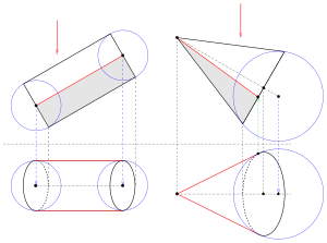
As a first example we choose a cylinder whose axis is parallel to the elevation table. The elevation appears as a rectangle and is therefore easy to draw. We incline the cylinder axis so that a clear picture emerges in the floor plan. We consider the cylinder to be the envelope of a set of spheres whose centers lie on the cylinder axis and whose radii are constantly equal to the cylinder radius. Since the outline in this simple case consists of two parallel lines, it is sufficient to look at two contact spheres (at the beginning and at the end, see picture). The floor plans of the centers of the spheres are easy to find using folders. The outlines of these spheres are two circles with the radius of the cylinder. The enveloping straight lines give the outline of the outline. Their outlines are just as easy using folders. Parts of the base and lid (elliptical arcs) also appear as outline parts.
Example cone
So that the elevation of the cone is easy to draw, the cone axis is chosen parallel to the elevation table. The cone can be imagined as the envelope of spheres with constantly increasing radii. The straight lines go through the tip of the cone and touch the contact ball on the bottom circle (see picture). The outline of this contact sphere in the plan is again a circle ("equator circle"), the center of which can be found via the associated folder on the plan of the cone axis. The tangents to this outline of the contact ball (in the plan) through the tip of the cone result in the desired outline of the cone. The boundaries of the contour lines in the elevation result either from folders from the floor plan or as a section of the "equatorial circle" (a line in elevation) of the contact sphere with the bottom circle of the cone.
Example torus
A torus can be understood as the envelope of a set of spheres with centers on a circle and constant radii. So that the elevation of the torus is simple and the floor plan provides a clear picture, we select the circle of the spherical centers perpendicular to the elevation table and tilted relative to the horizontal (see picture). The outline in elevation consists of two semicircular arcs and two parallel lines (envelope of the spheres). The circle of the center points appears as an ellipse in the plan. We select a sufficient number of contact spheres by choosing their center points (in the floor plan) and draw the corresponding ball outlines (circles in the floor plan). With the help of a curve ruler or "freehand", the outline of the torus in the plan (red curve) results as the envelope of these circles. It consists of two parts.
Example vase
The vase (see picture) is a surface of revolution. It is created by rotating the curves that can be seen in the elevation. So that the elevation is as simple as possible, we choose the rotation axis again parallel to the elevation table and tilted to the vertical. The surface of revolution can also be understood as the envelope of a set of spheres, the contact spheres, with variable radii. If you construct enough contact spheres (starting in the outline) and transfer their centers and outlines into the floor plan, the outline (in the floor plan) is the envelope of the associated circles. If you have roughly drawn the outline in the floor plan with a curved ruler, you can mark an outline point for each contact ball used in the floor plan, which can then be transferred to the corresponding "equatorial circle" of the contact ball in the outline using a folder. In this way, the outline of the outline (self-shadow limit) of the vase is also obtained.
Example of a single-shell hyperboloid
A hyperboloid of revolution can be generated as a surface of revolution by a suitable set of contact balls. However, since the single-shell hyperboloid also contains straight lines and is covered by a whole family of straight lines, one also has the option of depicting a sufficient number of lines whose endpoints lie on the bottom and top circle. The envelopes of these lines then form the outline of the hyperboloid (see picture).
Mathematical determination of the outline
Plane sections of a sphere
The plane section of a sphere is either empty, consists of a point or a circle. This is easy to see. What you need to calculate specific points is a parameter representation of the intersection circle, if a intersection circle exists (see weblink CDKG, p. 88).
Given: Sphere and plane Wanted: Parameter representation of the cutting circle .
The distance from the plane to the center of the sphere is .
- If is, the section is empty .
- If is, the intersection consists of a point .
- If there is, there is a cutting circle .
- a) The radius of the intersection circle is .
- b) The center is .
- c) In the following let and
- if or is, otherwise be . (This alternative guarantees an error-free choice of .)
- Too vertical radius vector is . So is
- a parametric representation of the cutting circle.
Outline of a sphere
We know that the true outline of a sphere is a circle in both parallel and central projection. Now a parametric representation of the outline is to be determined for a concrete projection. Initially with parallel projection. A distinction does not have to be made here between perpendicular and oblique parallel projection, since the true outline only depends on the direction of projection.
Given: sphere and a parallel projection with direction .
Wanted: Parametric representation of the true outline circle.
The true outline of a smooth surface separates visible points from invisible points. Whether a point is visible or not can be determined with the help of the normal vector (see below). Visible and invisible points can namely be recognized by the sign of the scalar product of the surface normal with the projection direction . Points on the outline provide the scalar product 0. The problem to be solved is somewhat reminiscent of an extreme value problem from school. As with the search for a global extremum, one must not rely on the points found with the outline condition (see torus, below). They could only be contour points locally. As with the extreme value problem, you also have to include the edges separately (see vase or cylinder).
For the sphere, a normal at a point is simply the position vector of that point. The outline condition in the point for the projection direction is:
This is the equation of a plane through the center (= zero point) of the sphere. With the above parametric representation of a plane section of a sphere, both the true outline (in space) and, after the projection, the apparent outline can be drawn. When projecting, it should be noted that a parallel projection (perpendicular or oblique) always represents a linear image. Therefore the center of the circle (of the true outline) is mapped to the center of the image circle / image ellipse and to conjugate radiuses of the image ellipse.
Now the outline of a sphere is to be determined with central projection:
Given: sphere and a central projection with eye point (projection center) .
Wanted: Parametric representation of the true outline circle.
The outline condition for a point is:
- .
This is the equation of a plane that does not contain the origin . The considerations for the intersection of a sphere with a plane also provide a parametric representation of the true outline in this case. Since a central projection is not a linear mapping, the statement about the center point and conjugate radius does not apply here. In the case of central projection, you should calculate enough points of the true outline and project them individually and connect them with a polygon (in the image table). Projection formulas for a central projection can be found in the article on central projection.
Outline of a paraboloid of revolution
Given: Paraboloid and a parallel projection with direction .
Wanted: the outline.
In this case it is not as easy to find a normal vector in a surface point as in a sphere, but if the paraboloid is represented implicitly by , then a normal vector is obtained for a surface point with the gradient . The outline condition is here:
- .
This is the equation of a perpendicular plane (parallel to the paraboloid axis). So the real outline is a parabola (see picture).
With considerations for the representation of plane sections of a paraboloid, as we did above for the sphere, a parametric representation of the section parabola can be given (see weblink CDKG, p. 94).
In the case of a central projection with an eye point (projection center) , the outline condition is :.
- .
This is the equation of a plane that is not perpendicular. Ie the true outline of the paraboloid is an ellipse with central projection (eye point "outside" the paraboloid) (see weblink CDKG, p. 98).
Outline of a single-shell hyperboloid of revolution
Given: hyperboloid and a parallel projection with direction .
Wanted: the outline.
We use the implicit representation again:
With is the outline condition:
- .
This equation describes a plane through the zero point (center of the hyperboloid). In contrast to the outline plane of a sphere, the outline plane here is not perpendicular to the direction of projection! (see weblink CDKG, p. 120).
In the case of a central projection with an eye point (projection center) , the outline condition is :.
- .
This is the equation of a plane that does not go through the origin. For a parametric representation of the true outline, considerations must also be made here about the possible plane sections of a hyperboloid (see weblink CDKG, p. 121).
Outline of a torus
A torus (ring surface) can be imagined by rotating a circle around an axis of rotation lying in the circular plane. A parametric representation that is similar to the parametric representation of a sphere can be derived from this idea. In order to recognize that the true outline is not a plane section, one can use an implicit representation (as with paraboloid and hyperboloid):
- .
If you calculate the outline condition here , you can see that it is not a plane equation . The equation describes a 3rd order area (3rd powers occur). So you can imagine the true outline as the intersection curve of the torus with a 3rd order surface. How to calculate individual points of this curve is shown in weblink CDKG, p. 139.
In the picture it can be seen that the local outline condition initially provides points that are covered by other parts of the surface. That means, after the calculation of outline points based on the outline condition, you have to test for each alleged outline point whether it is visible at all (see weblink CDKG, p. 131).
Outline of a polyhedron
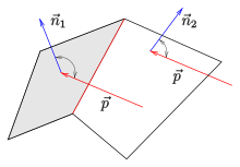
In the case of a polyhedron , the normal test (see picture) is used to test each (flat) sub-area to determine whether it is visible, and then determine the edges that belong to visible and invisible sub-areas. These edges form the true outline. Here, too, the real visibility of non-convex polyhedra still has to be checked with a hidden line algorithm (see weblink CDKG, p. 163).
literature
- Fucke, Kirch, Nickel: Descriptive Geometry. Fachbuch-Verlag, Leipzig 1998, ISBN 3-446-00778-4 . P. 165
- Graf, Barner: Descriptive Geometry. Quelle & Meyer, Heidelberg 1961, ISBN 3-494-00488-9 . P. 195
- Leopold, C .: Geometric basics of architectural representation. Verlag W. Kohlhammer, Stuttgart 2005, ISBN 3-17-018489-X . P. 129
Web links
- Descriptive geometry for architects (PDF; 1.5 MB). Script (Uni Darmstadt)
- CDKG: Computer-Aided Descriptive and Constructive Geometry (TU Darmstadt) (PDF; 3.4 MB), pp. 87–142


