
Star-delta starting circuit
A star-delta starting circuit ( YΔ circuit for short ) is used to start larger three-phase motors with squirrel cage rotors with reduced power consumption. This avoids the triggering of overcurrent protection devices due to the otherwise high starting current with direct start-up ( English Direct On-Line, DOL ) in delta connection .
In the starting process , the three-phase motor is first connected in star connection, then the motor is connected in delta connection. When starting in a star connection, the power consumption of the motor is 1/3 of the power in a delta connection.
The use of frequency converters has made the YΔ switchover largely obsolete. Larger asynchronous motors were often designed with slip ring rotors for starting . In contrast to the YΔ switchover, frequency converters can achieve reduced power consumption while still having a high starting torque.
execution
In practice, the star-delta starting circuit is implemented either with a contactor circuit or with a star-delta switch. With the contactor switching, the two contactors are electrically interlocked, because if both switch on, a short circuit occurs. The hand-operated star-delta switch is locked mechanically. The contactor circuit is usually controlled with a timing relay .
Conditions of use

Generally and in u. a. In Europe, the three-phase network with a voltage of 230/400 V, the following conditions must be met for the use of the star-delta starting circuit:
- Switching from star to delta connection may only take place after the motor has run up to 75 ... 80% of its nominal speed. If the switchover is too early, a strong current surge occurs and overcurrent protection devices can still respond.
- Due to the tightening torque of only one third, star-delta switching can only take place under light starting conditions (load-free flywheel, fans, pumps).
- Energy supply companies only allow the start-up circuit up to 11 kW (sometimes even higher).
- The start-up circuit can only be used with motors whose winding connections are not already connected internally, but are individually routed to the outside. This is usually the case when the jumpers in the junction box are removed.
- The star-delta starting circuit can only be used for motors that can be operated in a delta connection on the mains voltage. The motor windings must be able to withstand the line-to- line voltage between two external conductors, which is 400 V in Europe. The corresponding designation on the nameplate of motors that are suitable for star-delta starting on this network is "400/690 V", "Δ400 / Y690 V".
- If the motor is close to its nominal speed, it is switched to delta operation, the line-to-line voltage is 400 V across each winding. If the changeover does not take place or takes place too late, the motor can be overloaded if it delivers more than 1/3 of its rated power got to. That is, for example, upon starting of fans, fans or blowers typically given - the motor is ramped up to 2/3 of its nominal power in a star connection and must then be connected in delta.
Switching current peak

The star-delta starting circuit ( English Star-Delta , YΔ, AC motor / Wye-Delta) is used to limit the starting current of an asynchronous motor in a delta connection. The motor is brought up to speed in the star connection. When switching over, only the triangular current that corresponds to the current speed is required. In this way, the inrush current is reduced to 1/3 compared to the current with delta direct connection. However, when switching from star to delta, the mains phases and the motor field can be in opposition to one another. This leads to equalization processes, which can lead to a very high switching current peak.
Stress vectors
The switching current peak is dependent on the position of the new armature field (L1, L2, L3) to the newly built (L1 ', L2', L3 ') and the voltage of the collapsing rotor field (L1'-N). In the case of unfavorable combinations of interconnection and switchover pause, current peaks can occur that are higher than the starting current for direct delta switching. The result is that the correctly selected short-circuiting devices respond. Further consequences are welding or contact erosion on the contacts of the triangular contactor and high dynamic loads on the motor.
Depending on the external wiring of the outer conductors to the windings , the switching current peak can be up to twice the current in the case of direct connection to delta. This switching current is reduced by coordinating the switching pause and the interconnection.
A switchover pause is necessary in order to let the unquenched arc (switch-off spark) of the Y contactor collapse until the D contactor switches on. The recommended switching time is at least 50 ms. Non-stop switching is possible with special start-up electronics or an additional contactor and transition resistors.

Vector diagram of stator / rotor field voltages

Vector diagram of stator / rotor field voltages


Connection of the outer conductor to the motor windings

The following is an example of the interconnection of the main circuits
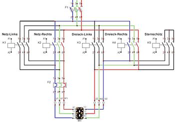
Star-delta reversing circuit, delta right-hand rotation colored

Star-delta reversing circuit, delta left-hand rotation colored


A main circuit with 5 contactors was chosen for clarity. Other circuits with fewer contactors are also possible.
Connection of a star-delta switch
A star-delta switch from VEB Elektroschaltgerätewerk Rochlitz (GDR, 1980s), for example, has bridges pre-installed so that only the mains voltage (RST) and the motor windings (UX, VY, WZ according to DIN) have to be connected:
| R → 1 | U → 2 | 3 | Z → 4 |
| S → 5 | V → 6 | 7th | X → 8 |
| T → 9 | W → 10 | 11 | Y → 12 |
According to IEC 6034-8 these are the following designations:
| L1 → 1 | U1 → 2 | 3 | W2 → 4 |
| L2 → 5 | V1 → 6 | 7th | U2 → 8 |
| L3 → 9 | W1 → 10 | 11 | V2 → 12 |
The columns of the table are arranged in the same way as the connections are usually arranged in the terminal box of the motor, whereby the terminals grayed out in the third column are not connected.
Web links
- Siemens - Basics of low-voltage switching technology ( PDF )
- EATON (Moeller) wiring manual ( download )
- EATON wiring book to turn the page ( wiring book )
literature
- Adolf J. Schwab: electrical energy systems . 2nd Edition. Springer, ISBN 978-3-540-92226-1 , pp. 919 .
Individual evidence
- ↑ Inaam Ibrahim: 10. Starting Method for Induction Motors. February 2012, accessed June 30, 2017 .
- ↑ http://www.moeller.net/binary/ver_techpapers/ver968de.pdf Start variants for the three-phase asynchronous motor, page 6, accessed on Nov. 14, 2017
- ↑ http://www.kimo.de/index.php?file=anwend/luefter/luefter.html&lang=DE Why power electronics for fan drives , website of KIMO Industrial Electronics GmbH, accessed on November 14, 2017.
- ↑ Electrical engineering journal . (CH) 2/1978, page 53.
- ^ L. Vercelli: Right and left rotation of the motors with YD start . Spokesman & Schuh AG, CH-5000 Aarau
- ↑ Siemens: Functional example no. CD_FE_III_001_DE.pdf, star-delta switching of three-phase motors - reducing the switching current peak .
- ↑ Moeller: Data sheet DIL power contactors
- ↑ Siemens: Switching, protecting, distributing in low-voltage networks . 4th edition, page 572.
- ↑ Siemens: Switching, protecting, distributing in low-voltage networks , 4th edition, page 574, figure 9.3 / 3.
- ↑ IS / IEC 60034-8: Rotating electrical machines, Part 8: Terminal Marking and Direction of Rotating ; Pages 6ff
- ↑ Moeller Eaton (Moeller) -Schaltungsbuch 2011 . Page 8–47
- ↑ Siemens: Switching, protecting, distributing in low-voltage networks . 4th edition, page 571