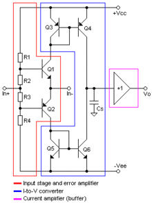
Current fed back operational amplifier
The current-feedback operational amplifier , as transimpedance operational amplifier designated (Engl. Current Feedback Amplifier, CFA), is a component of the electronics . It has an inverting ( - ) and a non- inverting input ( + ), as well as a voltage output. In contrast to the normal operational amplifier, the inverting input has a low resistance.
This type of operational amplifier should not be confused with the circuit of a transimpedance amplifier , which consists of an operational amplifier with a corresponding voltage feedback and is used to convert an input current into a proportional output voltage. Compared to the voltage-fed back OPV, the current fed back OPV does not lose its gain, especially at high frequencies. He is therefore z. B. used for video amplifiers. In return, the input currents are several orders of magnitude higher, which is partly put into perspective at higher frequencies due to the input capacities.
The basic internal structure of the current feedback operational amplifier can be divided into three sections:
- A buffer amplifier (voltage follower) buffers the voltage at the non-inverting input, its output goes to the inverting input. This part is framed in red in the basic circuit. This leads to a high impedance at the non-inverting input and a low impedance at the inverting input - the inverting input is actually a voltage output at which the same voltage is output as the non-inverting input.
- Two current mirrors replicate the current at the inverting output and thus apply a capacitor. This part is framed in blue in the basic circuit. As a result, the current is integrated at the inverting input and leads to a voltage rise that is proportional to the current.
- Another buffer amplifier at the output is responsible for the low output impedance. In the basic circuit it is framed in magenta.
The rise time and, indirectly, the bandwidth of the amplifier are mainly determined by the capacitance of the capacitor and the current at the inverting input. The capacitor makes the amplifier's transimpedance complex, with a resistive and a capacitive component. The transimpedance decreases with increasing frequency. The capacitor is usually very small and consists only of parasitic capacitances that result from manufacturing technology. In some cases, the manufacturer makes this node accessible at a connection, then the user can increase the capacity and thus reduce the bandwidth. However, this point is usually inaccessible from the outside so that the parasitic capacitances are minimal and the bandwidth and rate of rise maximal.
If a negative feedback connects the output with the inverting input, then the current at the inverting input depends on the size of this resistor. Since, as described, the current at the inverting input has an influence on the bandwidth, you can influence the bandwidth and indirectly the stability of the circuit by choosing the resistance value. In this respect, the behavior of the CFA differs significantly from the VFA. In practice, with the CFA, the feedback resistor is primarily selected according to the bandwidth requirements; the resulting overall gain is then determined by the second resistor in the negative feedback network.
Despite the low-impedance inverting input, the "golden rules" of the VFA also apply to the CFA, but in a slightly different way:
- The output tries to bring the voltage difference between the two inputs to 0 volts. With the CFA this is already guaranteed by the buffer amplifier at the input, it forces the inverting input to the same voltage as the non-inverting one. The output and the negative feedback are not needed for this.
- No current flows through the inputs. Strictly speaking, this is wrong with the CFA for the inverting input, but the negative feedback network indirectly ensures compliance with this rule, because the output assumes the voltage that ensures that the current at the inverting input goes to 0. With the VFA, this is already the case due to the high impedance of the inputs, without the output having to take care of the negative feedback.
For this reason, in many cases, the CFA can be used with the same feedback network as the VFA and then implements the same operation. The circuit development is thus largely the same for CFA and VFA. The differences mainly concern the areas of stability and frequency compensation , and the related bandwidth and slew rate.
Web links
- Current Feedback Amplifier Theory and Applications (English, PDF, 85 kB)


