Tooth width measurement
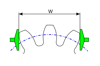
The tooth width measurement is used in the production of gears, to the thickness of the teeth of a gear to be determined. In addition, the tooth width can also be used for simple quality assurance tests on receipt of goods.
application
The tooth thickness has been able to be measured directly on a coordinate measuring machine (CMM) since the early 1990s . If this is not possible, the thickness is determined using an auxiliary dimension, e.g. B. over the tooth width. From this, conclusions can be drawn about the tooth thickness.
The measuring surfaces of the measuring device used must be in contact with the involute tooth flank. In particular, the measuring surfaces must not be in contact with the tooth tip corners or in the non-involute tooth root, otherwise incorrect values will result.
The number of measuring teeth, i.e. the number of teeth that must be held between the measuring surfaces of the measuring device, can be determined using a simple formula. Depending on the geometry of the gear (number of teeth, tooth height, pressure angle), one or more numbers of measuring teeth can be possible for measuring the tooth width. There are also gears or gears in which it is not possible to measure the tooth width, since the measuring surfaces of the measuring device do not rest on the tooth flanks for any number of measuring teeth. This is sometimes the case with toothing of splined shaft connections (also called splines ) that only have a small tooth height.
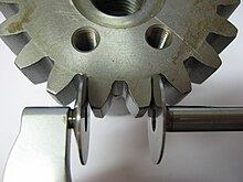
The tooth width can be measured on both straight-toothed and helical-toothed gears. Helical gears, however, must have a certain minimum tooth width, otherwise one of the measuring surfaces no longer touches the tooth flank and, as it were, hangs in the air. (see photo)
The tooth width can also be measured for internal gears. One speaks more of the gap width. The measurement of the gap width in internal gears is usually uncertain and inaccurate.
Measuring equipment
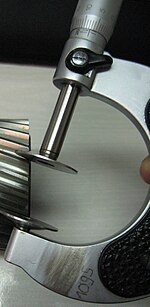
Outside micrometers are usually used to measure the tooth width, in which the measuring surfaces are designed as large plates.
However, as a makeshift measure, the tooth width can also be measured using a (digital) caliper. Measuring with a caliper requires experience, as the measuring jaws are easily tilted. With the circular micrometer, this is prevented by the wide measuring plate.
calculation
| size | character |
|---|---|
| Number of measuring teeth | (rounded to a whole number) |
| Straight tooth width |
with ( in radians!) |
| Number of measuring teeth and tooth width helical | Teeth z replaced by number of teeth with |
Calculation example
- Module 2.0 mm
- Number of teeth 36
- Pressure angle 20 °
- Profile shift factor x = +0.3
- Helix angle beta = 18 °
Results in:
- Number of measuring teeth z '= 6
- Tooth width W = 34.0473 mm
The calculated tooth width is the zero tooth width, i.e. the tooth width for backlash- free toothing. In gearboxes, there must be a certain amount of backlash between the teeth of the paired gears. Therefore, gears are always manufactured a little smaller than the calculated tooth width. For example 0.05 to 0.1 mm smaller.
The tooth width of an internal toothing is usually difficult to measure and is identical to the tooth width of the external gear that fits backlash-free and has the same number of teeth. Example: The internal toothing with module 2.0 and z = -30 has the same tooth width (actually: gap width) as the external toothing module 2.0 z = + 30. In the case of a profile shift , the sign must be observed!
Determination of the module of a gear with the help of the tooth width measurement
The module cannot be reliably calculated from the tip diameter of a gear , since the tip diameter depends on the profile shift, the helix angle and the selected tip shortening . In addition, the tip diameter is usually roughly tolerated in the design.
If you can measure two different tooth widths on a given gear, the module can easily be determined from this. To do this, however, the pressure angle must be known. With normal gear wheels it is usually 20 °. But there are also other pressure angles!
Visual Basic functions
These functions apply to straight and helical gears as well as internal gears!
Calculation of the number of measuring teeth:
Public Function MessZaehnezahl(Zaehne%, alfa#, beta#, x#) As Integer
'alfa und beta muessen in Grad uebergeben werden!

Const pi = 3.141592654
Dim alfas0#, alfasx#, betag#

alfa = alfa / 180 * pi 'Umrechnung von Grad in Bogenmass
beta = beta / 180 * pi

alfas0 = Atn(Tan(alfa) / Cos(beta))
alfasx = arccos(Cos(alfas0) * Zaehne / (Zaehne + 2 * x * Cos(beta)))
betag = Atn(Tan(beta) * Cos(alfas0))

MessZaehnezahl = Int((Zaehne / pi * (Tan(alfasx) / (Cos(betag)) ^ 2 - 2 * x / Zaehne * Tan(alfa) - (Tan(alfas0) - alfas0)) + 0.5) * 10 + 0.5) / 10

End Function
Calculation of the tooth width:
Public Function Zahnweite(Modul#, Zaehne%, alfa#, beta#, x#, messzaehne%) As Double
'alfa, beta muessen in Grad uebergeben werden!
Const pi = 3.141592654
Dim alfas0#

alfa = alfa / 180 * pi 'Umrechnung in Bogenmass
beta = beta / 180 * pi
alfas0 = Atn(Tan(alfa) / Cos(beta))

Zahnweite = Modul * Cos(alfa) * ((messzaehne - 0.5) * pi + Zaehne * (Tan(alfas0) - alfas0)) + 2 * x * Modul * Sin(alfa)

End Function
literature
- Verzahntechnik Lorenz GmbH & Co. (Ed.): Gear tools . 3. Edition. Ettlingen 1977.
- Heinz Linke: Spur gear teeth . Carl Hanser Verlag, Munich 1996, ISBN 3-446-18785-5 .
- G. Niemann, H. Winter: Machine elements . Volume II: Gear Transmission Basics . Springer Verlag, Berlin / Heidelberg 1989, ISBN 3-540-11149-2 .


