
gear

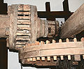
Herringbone spur gears that were in use for about 50 years.

The machine element gear is a wheel with teeth evenly distributed over the circumference . Two or more gear wheels paired with one another form a gear transmission . It is mainly used to transfer between two rotations or a rotation and a linear movement (pairing a gear with a rack ). Gear drives form the largest group among the drives . They are form-fitting and therefore slip-free .
If the transmission ratio is to be constant even on a small scale, i.e. from the engagement of the previous tooth to the engagement of the following tooth in the gaps of the mating gear , the first law of toothing must be observed. The positive fit is not lost if it is ensured that the following tooth is already in engagement before the engagement of the preceding tooth breaks off (second law of toothing) .
The shape of the teeth is basically arbitrary , taking into account the toothing laws. The shape selected for a meshing surface determines the shape of the meshing surface on the mating gear. In practice, one restricts oneself to tooth shapes that are easy to manufacture (thus also easy to describe geometrically). The involute toothing and the cycloid toothing are most widespread, each with its own advantages in use.
In addition to pure tooth pairings in gear drives, there are pairings between chain links and teeth of gear wheels in chain drives . Here chain links intervene in gaps between the teeth (for example in a bicycle chain on the sprocket and pinion ). In a toothed belt drive, the chain is replaced by a belt with teeth ( toothed belt ) ( e.g. for driving the camshaft in four-stroke engines ).
General
The gears of a gear train rotate together with the shafts on which they are mounted or turn on axles on which they are mounted .
The wheel spacing is designed in such a way that the teeth mesh with one another and thus the rotary motion of one gear is transmitted to the other. When pairing two externally toothed gears, the direction of rotation is reversed. If this is not desired, a third gear of any size is placed in between. If the wheels are of different sizes, the speed is increased or decreased, with the torque being decreased or increased (change of the gear ratio ).
history
Early Examples of Gears Uses
In the ancient Egyptian Göpeln one finds after 300 BC u. Z. the oldest form of the gearwheel, a wooden wheel, in the circumference of which pegs were stuck. The role was already in use with the Assyrians and was taken over by the Egyptians, the connection of these roles by means of rope led to the well-known pulley . A direct connection between these roles was already established in 330 BC. Mentioned in BC by Aristotle , the use of cogwheels at Heron of Alexandria is certain , handed down through Vitruvius . Ktesibios used around 250 BC BC a staff with cogwheels on his water clock, as did Philo of Byzantium around 230 BC. Chr. Gear wheels on two apparatuses. The most significant artifact for the use of gears in ancient times is the Antikythera Mechanism from around 100 BC. Chr.
Since the 9th century, gears have been used in water mills in Europe , and from the 12th century also in windmills . In Leonardo Da Vinci's manuscripts around 1500 gears can be found in various applications.
Georgius Agricola first indicated the use of iron gears in his work De re metallica libri XII in 1556 . However, an iron gear is on display in the Shaanxi Province History Museum in Xi'an , which is said to be around 2000 years old.
First considerations about the shape of the teeth
.jpg)
Initially, little attention was paid to the appropriate shape of the teeth. According to Christiaan Huygens and Gottfried Wilhelm Leibniz , the Danish astronomer Ole Rømer recommended the Epi-Cycloid as a tooth shape around 1674 . He was probably involved in the construction of his planetariums, e.g. B. the Jovilabium at the Paris Academie des Sciences came across it. There is no longer any written evidence for this. A first thorough mathematical investigation of these gears described the academician Philippe de La Hire (1640-1718) around 1694 Traite des epicycloides (published 1730). This epicycloidal tooth shape ensures uniform movement of the gears with uniform sliding friction. These were specifically built into clockworks. In 1759 John Smeaton developed his own form, followed by Leonhard Euler , who in 1760 proposed the involute for the tooth form ( involute toothing ).
Age of industrialization
The development of the steam engine in the 18th century led to an increasing need for gears, as the power to be transmitted increased continuously and gears had to be made of metal instead of wood, as was previously the case. In 1820 Joseph Woollams invented the helical gearing and herringbone gearing (double helical gearing ) (English patent no. 4477 from June 20, 1820), James White built a differential gear from them in 1824 . In 1829, Clavet manufactured a tooth planer, as machine tool construction required increasing gear accuracy from the 19th century. The first usable machine for milling spur gears was built by G. Grant in 1887. In 1897, Hermann Pfauter developed a universal machine from this that could also be used to manufacture worm and helical gears. From 1922 onwards, Heinrichschicht at Klingelnberg developed a process for manufacturing bevel gears ready for series production. What was new was that the continuous hobbing process could now be used here just as with spur gears.
- Spur gear and rack

Spur gear

Internally toothed (green) and externally toothed spur gear

Rack and pinion


Types of gears
Spur gear
The spur gear (or cylindrical gear ) is the most commonly used gear. A cylindrical disc is toothed on its circumference . The axes of a spur gear and its mating gear (spur gear or spur-toothed shaft ) are parallel, creating a spur gear . In addition to the spur gear as an outer gear, there is also the inner gear, which is not referred to as a spur gear, since the term "face" means an outer shape.
There are straight (axially parallel) gears, helical gears , double helical gears and various curved gears. In the case of double helical gears, a distinction is made between those with an undercut and those without, as true herringbone gears.
Rack
The rack can be imagined as a spur gear with an infinitely large diameter. The pairing of a rack with a spur gear is called a rack and pinion gear . The movement of the rack is straight and limited by its finite length. In common applications there is a back and forth movement.
The rack rail of a rack railway is an unusually long rack made up of many individual pieces .
Elliptical wheel

Most gear transmissions consist of round gears or wheel bodies with round pitch lines. When the driving wheel rotates smoothly, the driven wheel also rotates smoothly. An example of an unevenly geared gear, and thus consisting of non-circular gears, is an elliptical gear. An elliptical gear is a non-circular gear.
If two identical and equally large elliptical wheels are combined, the center distance is constant. The wheels each turn around one of their elliptical focal points . The transmission ratio varies over one revolution around the mean value i = 1. If only one wheel is elliptical, one wheel must be mounted on an oscillating axle. Such gears are used in weaving machines, for example . An elliptical chainring in the chain drive of bicycles is better known .
- Bevel gear and crown gear

Bevel gears
Crown gear: Spindle gear (spur gear, above) and crown gear (below)


Bevel gear
The axes of bevel gears are not parallel, but intersect. Usually the cutting angle is 90 °. The basic shape is a truncated cone , the outer surface of which is toothed. If two bevel gears are paired with one another, their tips coincide. The teeth usually run straight in the direction of the surface lines, with the so-called hypoid gear they are curved.
The tooth height profile of bevel gears corresponds to an octoid .
With spiral bevel gears a distinction is made mainly as follows:
- Circular arc toothing with non-constant tooth height (manufacturer Gleason )
- Circular arc toothing with constant tooth height (Kurvex)
- Cyclo-palloid toothing ( Klingelnberg )
- Palloid toothing (Klingelnberg)
Face gear
A gear with a crown gear is an angular gear and a variant of the bevel gear. In the past it was used more often than a bevel gear (see illustration: crown gear made of wood). In the case of a crown gear, the toothing is attached to the circular surface of a cylinder. Together with a spur gear, it forms a crown gear.

Worm wheel and worm
A worm gear made up of a worm wheel and worm is used alongside other gears when the shafts cross but do not intersect. Another feature is the relatively high gear ratio .
In the simplest case, the worm wheel can be a helically toothed spur wheel. The tooth flanks of the worm wheel are made hollow in order to achieve linear instead of point contact between the teeth in the gear.
The teeth on the small worm resemble a thread. The worm is like a spur gear with a few very angled teeth that are helically wound around the cylinder. One turn corresponds to one tooth. The thread-like toothing of the globoid worm is not cylindrical. The cylinder is waisted and adapts to the roundness of the worm wheel.
Basic types of gear drives
The gear transmission may be according to the position of the axes and the engaged wheels in rolling contact , and in helical divide.
Rolling gear

With rolling gears, the axes are either parallel (spur gear) or they intersect (bevel gear). When the motion is transmitted, imaginary roller cylinders or roller cones roll off one another without sliding. Sliding takes place only on the tooth surfaces in contact in the profile plane of the teeth (roller sliding) . The teeth touch in lines.
Helical gear
With helical gears, the axes are neither parallel to one another, nor do they intersect. The touching teeth also slide perpendicular to the profile plane (sliding perpendicular to the profile plane is the typical movement in the screw thread ). Helical gears are
- the helical gear, with the pairing of two helically toothed spur gears (point contact in the axis perpendicular),
- the worm gear with the pairing of a worm wheel and a worm (line contact) and
- the hypoid gear with the pairing of two helical bevel gears (point contact outside the perpendicular).
Tooth types - shape of the tooth flank

Involute gearing
- Use: when driving from fast to slow or vice versa (e.g. in vehicle and mechanical engineering ), the most important type of gearing
- easy normalization
- Pairs of wheels can be driven to the left and right with the same friction
- relatively low backlash gearing
- Insensitive to changes in the center distance, as the line of action is a straight line
- only rolling friction at the pitch point ; moving away from the pitch point increasing sliding friction
- The convex tooth shape creates a high surface pressure, which means a disadvantage in terms of service life.
- Manufacture of the gears relatively simple and inexpensive
- The involute toothing is a special case of the cycloid toothing, in which the rolling pitch circle has an infinitely large diameter during the construction of the cycloid and thus becomes a straight straight line . The resulting cycloid is then called an involute .

Cycloidal teeth
The flank of a tooth is an epicycloid above the pitch point and a hypocycloid below it .
- Use: When driving from slow to fast (e.g. with mechanically driven clocks ).
- When driving from slow to fast, there is less friction than with involute teeth.
- Larger transmission ratios in a small space are possible, as the teeth at the foot are narrower than with the involute toothing.
- Pure rolling friction is only possible from a certain minimum number of teeth on the smaller driven wheel.
- Normalization difficult because the tooth shape, compared to the involute, also depends on the number of teeth on the smaller driven gear. In order to achieve ideal meshing and friction conditions, the tooth shapes of a pair of gears have to be specially coordinated. Standardization compromises have been made in watchmaking.
- Larger tooth clearance (more dust tolerant).
- Forward-backward running is not possible: A rotary movement is only possible in one direction. The reasons are a significantly larger backlash than with involute teeth and different friction conditions for different directions of rotation.
- Only the wheel bearings are lubricated, the wheels themselves are operated dry to prevent the accumulation of dirt.
- The depth of engagement is more critical than with involute teeth. In watchmaking, the mathematically determined distance is insufficient as an ideal. It is also adjusted empirically (must be felt).

Rack gearing

The headstock toothing is a special case of the cycloid toothing: the pitch circle and pitch circle are the same size.
- Use: e.g. B. old mill wheels, Black Forest clocks , racks, roller chains
- Application largely displaced by the involute and cycloid teeth. An earlier advantage of this gearing was the easier manufacture of wheels. In addition, a sufficiently accurate division was easy to achieve using a drilling template.
The toothing can be straight, i.e. H. axially parallel, at an angle ( helical toothing ) or as curved toothing . The size of the toothing is determined as a module . The mating gear must have a toothing of the same module.
Wildhaber-Novikov interlocking
The Wildhaber-Novikov toothing is a circular arc toothing.
- Use: in face gears (running gears).
- Convex, semicircular teeth engage in concave gaps of the same shape. The theoretical radius of the tooth and the tooth gap is the same, in practice the tooth gap radius is slightly larger.
- No profile overlap can be realized, for an even transmission of motion a helical toothing with a jump overlap> 1 is required. The pressure angle is constant in every tooth position, so that the tooth force does not change direction.
- The good fit of the tooth and tooth gap due to the design has an advantageous effect. Further advantages are the good load-bearing capacity (higher than involute teeth), the uniform wear (low relative movement of the flanks to one another) and the favorable noise and vibration behavior.
- This gearing is critical in the case of geometrical deviations such as pitch and tooth direction errors as well as center distance and axis inclination deviations.
- The manufacturing effort is great because different gear cutting tools are required for the wheel and the mating wheel.
Geometric sizes on straight spur gears

With the ratio suitably chosen number of teeth and the module is pitch circle diameter determined.


- The tip diameter is two tip heights of the teeth larger than the pitch circle diameter.
- The root diameter is two feet heights and the head clearance smaller than the pitch circle diameter.
- A common value for head height is .
- A common value for foot height is .


The three circle diameters are calculated from these specifications as follows:


With internal toothed ring gears , when using the equation, it should be noted that the number of teeth is negative and therefore negative diameters result. The root diameter of a ring gear is larger than the tip diameter.
The pitch of the toothing is the length of the arc from tooth center to tooth center on the pitch circle (also called pitch circle ):

- ( ... is the definition for the module).


The distance (center distance) of the axles of the paired externally toothed wheels 1 and 2 give the following equations:

- or


The module for spur gears is to be selected in accordance with DIN 780-1.
All information only applies to gears without profile shift , i.e. H. uncorrected gears.
Manufacturing

The manufacture of gears can be done in three ways:
Due to their higher strength and accuracy, machining processes are preferred in the industrial manufacture of gear wheels.
Machining processes

Overview
The machining processes for gear manufacturing are:
- with geometrically determined cutting edge
- Hobbing
- Hobbing , the most important process for rough machining
- Profile milling
- Gear shaping
- Skiving
- Profile broaching
- Scrape
- Free -form milling / 5-axis milling
- with geometrically undefined cutting edge
- Generating and profile grinding (variants of grinding )
- Honing
- Lapping


In profile milling and grinding, the tool has the exact shape of the tooth flank. When rolling , a tool is guided by the manufacturing machine in such a way that it "rolls" with the tooth flank to be produced. The material is only removed at one point or on a line. Here one tool can be used for many different tooth geometries, but the kinematics and thus the control of the machine is relatively complicated. When traversing a profile , a large number of different tools are required or the grinding wheel has to be brought into the shape of the tooth flank before it can be used ("dressing" the grinding wheel). Rolling processes can be carried out continuously, i. H. the entire gear wheel can be manufactured in one continuous movement (e.g. using a worm-shaped milling cutter). Profile processes always work in the partial process, so only one tooth gap can be produced at a time, after which the work wheel is turned one further gap.
Freeform milling
For some years now, free-form milling or 5-axis milling has been increasingly used on machining centers for single part production or small quantities . The basic idea is based on the knowledge that a gear is ultimately nothing more than a shape - comparable to tool and mold making - but with a complex tooth geometry. For this purpose, non-profiled, independent solid carbide tools that are detached from the gear data of the workpiece are used. Typical gear cutting tools such as hobs and side milling cutters, cutting wheels, planer combs and planing steels, cutter heads with bevel gear cutting knives, bevel gear cutters, worm gear hobs are no longer necessary.
In principle, different gear types can be produced on the same 5-axis simultaneous machining center in soft and hard machining (± 62 HRC). The 5-axis simultaneous capability ensures that non-profiled end mills can be used for the finishing of helical gears and spiral gears, instead of tedious milling with a spherical cutter.

As a rule, separate CAM software is used for milling programming, which focuses on milling free-form surfaces and can therefore also be used excellently for tooth profiles. Depending on the type of workpiece, the gear module and the resulting size of the tooth gap, individual milling strategies for roughing, tooth root and finishing can be selected.
Primary forming and reshaping manufacturing processes
Gears can not only be produced by machining processes, but also by primary forming and forming processes. However, these manufacturing processes play a subordinate role in comparison to machining processes.
Gears can be molded by casting or sintering ; Injection molding is used for plastic gears . The main application is precision engineering , where no large torques have to be transmitted. Small gears are also etched (similar to lithography ) or galvanized.
Forming processes such as forging , pressing , drawing, rolling ( ring rolling ) or punching are used if there are no high demands on accuracy. Forged gears are also used in large-scale technical applications, for example the bevel gears of differential gears in vehicle construction are produced by drop forging .
Post processing and heat treatment
Gears are often hardened after they have been cut . As a result, the tooth flanks become more wear-resistant, especially against so-called pitting , and the gear wheel can withstand higher loads and last longer. However, hardening distortion occurs during hardening, which is why the flanks usually have to be reworked after hardening by grinding in order to achieve the desired gear quality.
Construction / CAD
The construction of gears is computer-aided using CAD . 2D drawing data and machine setting data sheets are required for gear production using hobbing processes, and 3D drawing data are required for gear production using free-form milling. Gears are not designed manually on the basis of point clouds, but with specially developed software . This ensures that the gears mesh properly during operation. In addition to the mathematical calculation, some programs also offer a simulation of the kinematics during production, for example to avoid unintentional undercut .
Checking gears
General
The inspection of gears is extensive and depends on the type of gear. In the gear wheel test, the various parameters of gear wheels are determined using conventional length and angle measuring methods and special gear measuring methods. For safety-critical applications, material testing methods such as X-rays or scanning with particle accelerators are used during the final production test.
Checking bevel gears
The testing of bevel gears is carried out mainly by running tests. Using a running test machine , the bevel gear to be tested is brought into mesh with a master gear and rolled at the target center distance, target axis angle and target speed. The later function in the transmission is actually simulated.
The quality of the bevel gear is assessed by the resulting contact pattern, the noise generated during the running test and the circumferential backlash.
In running tests, a distinction is made between two-flank rolling tests and single-flank rolling tests.
Supplementary tests are still the concentricity test with concentricity test devices and the tooth thickness test with tooth thickness measuring devices. The rapid development of test methods can also be seen in bevel gear testing. The use of coordinate measuring machines has now also had a major impact on bevel gear testing. The topography of the bevel gear is determined with the appropriate software, and the contact pattern and circumferential backlash are calculated and simulated. Correction values are forwarded directly to the bevel gear milling machine (closed loop).
With traditional production on bevel gear milling machines, there are generally more or less large deviations between the theoretical calculations and the practical milling result. In the case of 5-axis milling on 5-axis simultaneous machining centers, such subsequent corrections are usually not necessary, as the milling result and therefore the position and size of the contact pattern correspond to the calculation right away due to the manufacturing method.
Checking spur gears
The most important basis for the testing of spur gears is the DIN ISO 1328 standard, in which the tolerances for spur gear teeth are specified.
Different test methods are used depending on the quality requirements.
Compliance with the correct tooth thickness is crucial for the function of a spur gear. However, direct measurement of the tooth thickness is not possible, so to determine the tooth thickness, the tooth width or the dimension is measured using two measuring rollers inserted in opposing tooth gaps (measurement of the roller dimension) . For the manufacture of spur gears, the designer usually specifies the tooth width or the roller dimensions with corresponding tolerances.
When manufacturing spur gears, the tooth width is almost always the manufacturing dimension to be adhered to and therefore the tooth width of almost all cylindrical gears is measured directly on the machine. The tooth width can also be measured with micrometers while the gear is still clamped.
In the double flank rolling test , the test object is brought into play-free engagement with a movably mounted master gear and rolled.
The resulting changes in the center distance are registered and evaluated as two-flank generating deviation and two-flank generating jump. Only total deviations are determined, i.e. H. The causes of errors are sometimes difficult to identify. In terms of geometry, the master gear must match the test object, i.e. it must generally have the same module. This method is less suitable for gears with high quality requirements. The rolling test can be easily integrated into production processes. The single-flank test procedure is comparable to the double- flank test . The assignment of the deviations to the right or left flank is advantageous in this test method.
The determination of the individual defects of a spur gear is the safest and most precise method for determining quality. With special gear measuring machines and also with coordinate measuring machines and corresponding software, the profile, flank and pitch deviations as well as the tooth width are determined and evaluated in the measurement protocol. This measuring process takes place automatically. The toothing quality of the gear can be determined from the measured tooth deviations. A targeted correction of the processing machine is then possible.
Toothing qualities
According to DIN 3961 (withdrawn) there are 12 toothing qualities that can be achieved with different production methods, 1 being the finest and 12 being the coarsest toothing quality.
Manufacturing process:
- Quality 1-6 honed
- Quality 1–7 sanded
- Quality 5–7 scraped , ( cold rolled )
- Quality 5–9 hobbed , hobbed , hobbed
- Quality 7-12 die milled , shape encountered , cleared
- Quality 8–12 punched, pressed, sintered , injected
Types of damage

The following damage can occur:
- Pitting ( pitting )
- Tooth breakage, mostly in the area of the tooth root
- Micropitting (micro-pitting)
- Eat
- Wear (at slow speed)
See also
- Planetary gear
- Pawl
- The hypoid drive is a special bevel gear .
- The chainring and pinion of a bicycle are also referred to as gear wheels , for the special features of this type of power transmission, see chain transmission
- Chain hoists and (chain) differential pulley blocks have chain sprockets and sprockets that engage in round chains like cogs
- Duplex worm , the backlash-adjustable variant of worm gear teeth
literature
- High tech from ancient Greece. In: Basler Zeitung , December 1, 2006, p. 40.
- Henry C. King: Geared to the Stars. The Evolution of Planetariums, Orreries, and Astronomical Clocks. In collaboration with John R. Millburn. University of Toronto Press, Toronto et al. 1978, ISBN 0-8020-2312-6 .
- Jan Klingelnberg (Ed.): Bevel gears. Basics, applications. Springer, Berlin et al. 2008, ISBN 978-3-540-71859-8 .
- Heinz Linke: Spur gear teeth. Calculation, materials, manufacturing. Hanser, Munich et al. 1996, ISBN 3-446-18785-5 .
Web links
Individual evidence
- ↑ With the simple friction wheel pairing , slip cannot be avoided.
- ^ Albert Neuburger: The technology of antiquity. R. Voigländers Verlag, Leipzig 1919, p. 221 .
- ^ Albert Neuburger: The technology of antiquity. R. Voigländers Verlag, Leipzig 1919, p. 212 .
- ↑ Franz M. Feldhaus : The technology of the prehistoric times, the historical time and the primitive peoples. A handbook for archaeologists and historians, museums and collectors, art dealers and antiquarians. Wilhelm Engelmann, Leipzig et al. 1914, Sp. 1341 .
- ↑ Franz M. Feldhaus: The technology of the prehistoric times, the historical time and the primitive peoples. A handbook for archaeologists and historians, museums and collectors, art dealers and antiquarians. Wilhelm Engelmann, Leipzig et al. 1914, column 1345 .
- ↑ Hans-Wilm Schütte: China 6th edition, completely revised. and redesigned. Baedeker, Ostfildern 2006, ISBN 3-8297-1109-3 .
- ^ Hans-Wilm Schütte: China. The travel guide from the specialist. 2nd, revised edition. traveldiary.de Travel Guide-Verlag, Hamburg 2012, ISBN 978-3-941796-31-7 .
- ↑ Franz M. Feldhaus: The technology of the prehistoric times, the historical time and the primitive peoples. A handbook for archaeologists and historians, museums and collectors, art dealers and antiquarians. Wilhelm Engelmann, Leipzig et al. 1914, column 1347 .
- ↑ Company history of Gleason-Pfauter
- ^ Deutsches Museum: Gear hobbing machine, spur and worm gears, 1912 .
- ↑ Klingelnberg company history
- ^ Deutsches Museum: Gear hobbing machine, spiral bevel gears, 1923 .
- ^ Siegfried Hildebrand : Feinmechanische Bauelemente. Hanser, Munich 1968, p. 488.
- ↑ tec-science: Geometry of cycloid gears. In: tec-science. December 21, 2018, accessed on November 10, 2019 (German).
- ^ Herbert Wittel, Dieter Jannasch, Joachim Vossiek, Christian Spura: Roloff / Matek. Machine elements. Standardization, calculation, design. 24th, revised and expanded edition. Vieweg, Wiesbaden 2019, ISBN 978-3-658-26279-2 , pp. 763-765.
- ^ Berthold Schlecht: Machine elements. Volume 2: Gears - Toothings - Bearings. Pearson Studium, Munich et al. 2010, ISBN 978-3-8273-7146-1 , p. 376 .
- ↑ a b Georg Jacobs (Ed.): Maschinengestaltung Volume II. Verlag Mainz, Aachen 2016, ISBN 978-3-86130-749-5 , pp. 123–128.