Worm gear


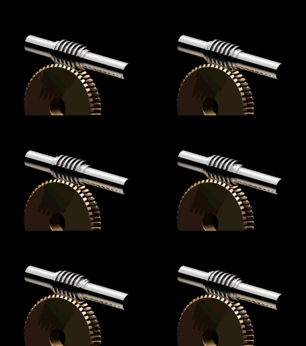
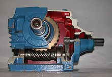
A worm gear is a combination of helical and gear transmission and comprises a screw-shaped so-called worm shaft and a gear, the so-called worm wheel . The thread of the worm shaft engages in the gaps between the teeth of the worm wheel.
In contrast to the gear drive, which sometimes only has rolling contact, permanent sliding contact takes place here, as in a helical gear. This is the main reason for the relatively low efficiency for high gear ratios and the cooling of such a transmission that is usually necessary. But it is also the reason that the worm gear is the quietest and a gear drive with a relatively high load capacity.
Structure and application
A worm gear consists of a shaft with one or more helical turns, the worm, and a helical gear, the worm gear, meshing with it. The axes of the two are mostly offset by 90 °. Special areas of application for such a gearbox are where high reductions (up to 150) and / or self-locking are required in one step . There are left- and right-handed snails. Both directions of rotation are equally possible. Most applications are driven by the worm.
The gear ratio is calculated as the quotient of the number of teeth z2 of the worm wheel by the number of turns z1 of the worm. When driven by the worm, the speed is converted to slow speed, when driven by the wheel, however, the speed is increased (only possible with non-self-locking pairings).
Self-locking occurs due to the sliding friction between worm and worm wheel, but only with a high gear ratio, low number of turns and a helix angle of <5 °. It has the effect that the speed can only be greatly reduced by means of self-locking worm gears , but not increased significantly. This effect can also be used to make the required brakes on gearboxes for elevators or chain hoists smaller. For safety reasons, self-locking cannot replace a brake.
Worm gears are used as power gears in presses , in rolling mills , in conveyor technology, in mining machines and rowing machines , but also in precision design as duplex worms in milling heads and rotary tables.
Further applications are actuators , e.g. B. in multi- speed trimming resistors , and especially in the past steering gears for motor vehicles .
Examples of the translation into high speed are mechanical drives for centrifuges in dairy machines, rotary dials and aerodynamic brakes or centrifugal governors in gramophones and music boxes .
The snail
In general, the worm is a special form of a helical gear . The angle of the helical toothing is so large that a tooth winds helically around the wheel axis several times. The tooth in this case is called a gang . There are single or multi-flight snails. The usual materials for screws are case-hardened or nitrided steels. The surface is given a wear-resistant layer through case hardening or nitriding .
The worm wheel
Worm gears consist predominantly of Sn bronzes (CuSn) and are manufactured from a certain size as wheel rims for reasons of cost, which are mounted on cheaper base bodies (e.g. made of cast steel). The production takes place in the continuous casting GC for small and subordinate gears or as centrifugal casting GZ with higher strength requirements in the gearing area. Due to its good emergency running properties in connection with steel, bronze is suitable for gearbox construction. In the case of high torques to be transmitted, special brass or aluminum bronze is used. It should be noted here that the sliding speed must be greatly reduced compared to the Sn bronze wheels.
species
- Cylindrical worm gear
The basic body of the worm has a cylindrical shape and the worm wheel has a (globoidic) curvature corresponding to the diameter of the worm. The advantage here is the simpler manufacture of the screw, which is why this type is also the most common and is also referred to as the "standard shape".
- Globoid worm gear
Here the worm has a globoid shape and the worm wheel is cylindrical. The possibility of using a conventional helical toothed gear as the worm wheel brings great advantages, but the manufacture of the worm becomes much more complex.
- Globoid gear
This is a special design in which both the worm and the worm wheel are designed as globoid bodies. Due to the high manufacturing cost of the worm gear, these are only used as individual pieces and in special cases and are usually not produced in series.
- OTT helical gear: worm
gear with adjustable backlash The worm consists of 2 parts in this version: a shaft worm and a hollow worm. The play between the worm and the worm wheel is adjusted by turning the two worm parts. The teeth are designed so that only one side of the worm tooth is attached to the wheel tooth.
-
Duplex worm gear : worm
gear with adjustable clearance, worm shaft with two different pitches / modules on the leading and trailing edge. By axially readjusting the worm shaft relative to the worm wheel, stronger worm windings are brought into engagement with little play. In proportion to the gear ratio, several teeth also wear at the same time.
Materials and lubrication
The manufacture of worm gears places increased demands on the production process in terms of manufacturing accuracy and surface quality in order to reduce friction . For the same reason, the worm and worm wheel are made of different materials; while the screw exposed to greater wear z. B. made of hardened steel, the worm wheel is often softer and consists of brass , bronze or a self-lubricating plastic.
Exposed worm gears are lubricated with grease, with closed housings oil can also be used for lubrication. So z. B. synthetic oils based on polyglycol are used for lubrication. In the case of special brass or aluminum bronze, PG oils are out of the question, only mineral oils can be used here. The oil supply must be based on the design of the housing and the intended heat dissipation ( splash lubrication / circulating lubrication ).
Since worm gears can heat up in continuous operation due to the low efficiency at high gear ratios, another task of the lubricant is, as in other gears, to transport the heat away. If he can easily transfer this to the housing, which is ribbed for this purpose, or if it is even blown on by a fan, the oil supply may be lower.
Construction requirements
Since the worm is toothed in a helical manner, but is firmly mounted, high axial forces occur. Depending on the operation, whether only in one direction of rotation or in both, the corresponding pages are z. B. adequately supported with axial bearings . The same conditions for helical spur gears apply to the worm gear.
It should also be noted that the worm is also subjected to bending loads and that the bearing must be designed to be elastic or to compensate for angles accordingly. Correct meshing in the event of a change in the center distance caused by bending is only guaranteed when using worms with involute flanks. With hollow-flanked screws, the deflection can cause harmful edge wear.


