
Steering gear


_(14597343157).jpg)

The steering gear is part of the steering system of a motor vehicle and converts the turning movement of the steering wheel into a sliding movement of the tie rods . With rack and pinion steering , the tie rods are moved by a transversely shifted rack, with steering gears with a pitman arm, by the pivoted pitman arm.
history
The first steering gear comes from Carl Benz : a hand crank transmitted the steering movements to the front fork via a steering column (shaft), a pinion and two racks. The screw spindle steering was developed by Daimler for the standard 3-ton truck .
In the following years worm and screw spindle gears were developed, so that in the 1920s a distinction was made between steering gears according to these two types. In the 1930s, rack and pinion steering was added in Germany, especially in front-wheel drive vehicles , including DKW Meisterklasse and Adler Trumpf . The development of the recirculating ball steering system (a screw-spindle steering system with rolling friction) that began at General Motors in 1940 was taken over by ZF in 1953 and installed, for example, in Mercedes-Benz cars . Today in passenger cars, the steering rack and uses the recirculating ball steering system for commercial vehicles, usually with power assistance .
Classification
Rack and pinion steering
The rack and pinion steering contains a rack and pinion gear . A pinion rotated by the steering wheel moves the rack and this the tie rods. The rack is pressed against the pinion via a spring-loaded pressure piece in order to avoid play. The rack and pinion steering consists of a few parts (no intermediate parts between rack and tie rods), which is why it is cheap to produce and easy to assemble. Today it is used almost exclusively in passenger cars and is often hydraulically or electrically assisted because of the great steering force of modern vehicles and the generally increased demands on operation . A distinction is made between rack and pinion steering systems with center tap - both tie rods converge in the middle of the vehicle and are attached next to each other at the end of the rack - and with side tap, that is, a tie rod is hinged to each end of the rack. Center tapping is typical for rack-and-pinion steering mounted high (on the bulkhead ) on spring or damper strut front axles and suspensions on swing arms, side tapping is found on double wishbone axles , but also on suspension strut axles, then the steering is installed far below, roughly at the height of the wishbones. Due to the arrangement with the longest possible tie rods or the same length of the tie rod and handlebars, the toe-in changes only slightly during compression.
Worm steering
The worm steering works with a worm gear . A worm is turned with the steering wheel, which turns the worm wheel, reduced to one sector, with the pitman arm and moves the tie rods mounted on the pitman arm. There were different designs of worm steering, more compact or with reduced friction:
- With finger or Ross steering , the worm wheel is designed as a crown wheel . One or two steering fingers with a round cross-section serve as teeth. They stand parallel to the pitman arm shaft and engage laterally in the worm. With a given ratio, the distance between the steering shaft and the pitman arm becomes smaller. David E. Ross received a patent for this design in 1925. If only a single finger is engaged, the pitch of the worm thread can be changed from the center outwards (variable steering ratio, for lower steering forces when the wheels are turned). Steering fingers can be permanently mounted, but can also be rotatably mounted about their axis in order to reduce the steering forces due to the lower rolling friction resistance in contact with the worm. The Ross steering was first installed in commercial vehicles in 1927, ZF Friedrichshafen received the patents for Germany and manufactured Ross steering under license from 1932 to the 1970s. Maurice and Georges Sizaire received a patent in 1914 for a similar design with a worm and ball-bearing steering finger.
- The roller or Gemmer steering (after the manufacturer Gemmer Manufacturing Co. in Detroit) is a design developed by Henry Marles. In 1920 Marles applied for a patent, which he received in 1926. It is also called worm steering with a swivel castor . The worm wheel is designed here as a roller with two or three circumferential teeth, which is mounted on the shaft of the pitman arm. In the straight ahead position of the steering, the axis of the roller is parallel to the worm shaft. The worm shaft is designed as a globoid worm, that is, its diameter increases towards the ends so that it can intervene in the roller over the entire steering angle. ZF Friedrichshafen acquired the patents for Germany in 1953 and manufactured the Gemmer steering under license.
- The Bishop steering is similar to the Ross steering. Here the fixed finger carries a roller bearing roller, which means that the groove of the worm shaft has to be wider. The corresponding patent was granted to the British engineer Reginald Bishop in 1928.
Screw steering
With screw spindle steering, turning the spindle screw from the steering wheel moves a spindle nut (the steering nut ). The nut is either designed on the outside as a toothed rack which engages in a corresponding gear fixed on the pitman arm, or it is connected via a pin to a lever on the shaft of the pitman arm. The tie rods are shifted from the pitman arm. Often there is no adjustment option in this steering gear and the friction is high. An adjustable spindle steering was used in the VW Beetle until 1961. The hemispherical spindle nut sat in a corresponding socket on the pitman arm shaft and was pressed from above against the threaded spindle.
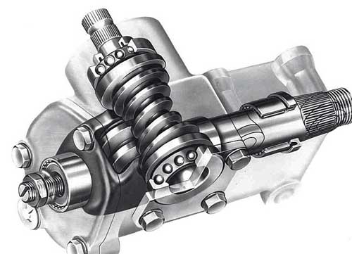
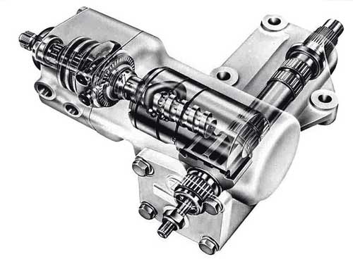
Recirculating ball steering
The recirculating ball steering or ball nut steering is a particularly smooth screw spindle steering. It contains balls rotating on the thread path between the spindle screw and nut ( ball screw drive ). The rolling resistance of the rolling balls is much lower than the sliding friction in the thread of a helical gear. The recirculating ball steering was also used in mid-range and luxury cars (for example in the Mercedes-Benz 124 series ), but now it is almost only used in commercial vehicles with hydraulic servo assistance ("hydraulic steering").
literature
- Olaf von Fersen (ed.): A century of automobile technology. Passenger cars. VDI Verlag 1986, ISBN 3-18-400620-4 .
- Olaf von Fersen (ed.): A century of automotive technology - commercial vehicles. VDI-Verlag, Düsseldorf 1987, ISBN 3-18-400656-5 .
- Rolf Gscheidle: Expertise in automotive technology. 30th edition, Verlag Europa-Lehrmittel, Haan-Gruiten 2013, ISBN 978-3-8085-2240-0 .
- Jörnsen Reimpell: (Hrsg.): Chassis technology: steering systems and power steering systems. Vogel Buchverlag Würzburg, 1st edition 1992, ISBN 3-8023-0431-4 .
- Peter A. Weller: Expertise in automotive technology. 2nd edition, Holland + Josenhans Verlag, Stuttgart, 1982, ISBN 3-7782-3520-6 .
Web links
Individual evidence
- ↑ Jörnsen Reimpell: (Ed.): Fahrwerktechnik. P. 67.
- ↑ a b Olaf von Fersen: A Century of Automobile Technology - Passenger Cars., P. 390, 391.
- ↑ a b c d Olaf von Fersen: A Century of Automobile Technology - Commercial Vehicles., P. 176, 177.
- ↑ US patent 1120096 by Maurice and Georges Sizaire (1914)
- ↑ US Patent 1425753 by HM Denyes (1921)
- ^ Curt Hanfland: The modern mechanical engineering . Verlag der Literaturwerke "Minerva", Volume 2, Leipzig 1928, p. 344.
- ^ Peter A. Weller: Expertise in automotive technology. P. 262.
- ^ A b Rolf Gscheidle: Expertise in automotive engineering., P. 481.
- ↑ Karl-Ludwig Haken; Basics of automotive engineering; ISBN 9783446228122 p. 101
- ↑ Picture of a Ross steering: [1]
- ↑ U.S. Patent 1567997
- ↑ zf.com From muscle power to autonomous. (accessed on June 14, 2016)
- ↑ https://patentimages.storage.googleapis.com/pages/US1120096-0.png
- ↑ U.S. Patent 1584629
- ↑ Pictures of Gemmer steering systems: [2] , [3]
- ↑ U.S. Patent 1673488
- ↑ Bishop Cam Steering Box - GB 223963, [4]
- ↑ Ball screw technology, [5]
- ↑ Pictures of the recirculating ball steering system [6] , [7]
![[1]](http://www.oldtimertechnik-rubenbauer.de/6411_g.jpg)
![[2]](http://www.02-club.de/technik/fahrwerk/gemmer.jpg)
![[6]](http://www.oldtimerlenkungen.de/6409_g.jpg)
![[7]](http://www.fordmuscle.com/archives/2002/07/steeringbox/images/reball.gif)