
Pulley
A pulley block is a machine that determines the amount of force to be applied e.g. B. for moving loads reduced. The pulley system consists of fixed and loose pulleys and a rope . In the case of complicated pulley blocks, the rollers are combined to form a block using "scissors".


history
The reduction of force through the application of the law of levers was already known in ancient times . The inventor of the pulley block is not known (possibly Archytas ), but the invention of the composite pulley block is attributed to Archimedes . A first pictorial representation of the combination of rope and simple pulley can be found on an Assyrian relief around 970 BC. Chr.
Dugout cranes braced with ropes that ran over three ("Trispastos") or five pulleys ("Pentaspastos") have been around since 750 BC. Known.
- For the history of the crane, see History of the Cranes .
Vitruvius , a Roman architect, engineer, and architectural theorist of the 1st century BC BC , described in his 10th book on mechanical engineering in detail the Trispastos, Pentaspastos and Polyspastos. At that time, however, it was hardly possible to produce ropes for pulley blocks with a large number of pulleys in the required length and load-bearing capacity, or the required number was almost unaffordable.
The Greek mathematician and engineer Heron of Alexandria probably lived in the 1st century and also dealt with the pulley block. During the brisk construction activity of the Roman emperors , the construction crane was indispensable for erecting the arenas . Thanks to various pulleys, the operating teams were able to lift stone blocks weighing up to seven tons. In the 6th century, around the year 530, a sand-lime stone monolith with a weight of 230 tons was used as the keystone of the domed roof for the mausoleum of Theodoric near Ravenna by means of complicated pulleys by 700 workers to a height of 16 meters. Even Leonardo da Vinci did in his inventions (eg. In the Codex Atlanticus , Codex Forster II & III) the pulley advantage.
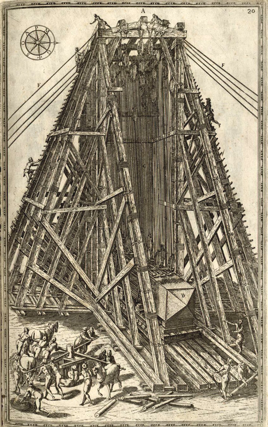
During the Renaissance , the pulley system found its most spectacular application in the transport and erection of the obelisk in St. Peter's Square in Rome from April 30 to September 16, 1586 by the engineer Domenico Fontana . 907 workers and 75 horses turned the 40 capstans , using pulleys on ropes up to 220 meters long to pull the 40 pulleys hanging from a gigantic wooden frame to bring the 330-tonne and 25.31-meter-long obelisk into a vertical position.
The pulley system and its use remained largely unchanged until 1861. It was only with the differential block and tackle , used for the first time in London, that an increase in efficiency could be achieved. Today pulley blocks are mainly used in cranes or tensioning devices (wheel tensioning systems) for contact wires .
Functional principle and parts of the pulley
A pulley comprising at least one loose roller ( pulley ) and a rope. The functional principle is shown in the picture on the left (explanation of the pulley system). In A, a weight with the mass m is pulled up, whereby the upper roller only deflects the force and thus the weight is lifted by exactly the distance that the rope is pulled (blue marking and blue arrow). In B a simple pulley block is shown with the rope attached to the upper beam and the weight hanging from a pulley in the rope loop. If the rope is pulled the same length as in A, the weight only increases by half. The rope parts to the left of the rope section that is being pulled must be shorter by the total length of the pulling distance, which, however, is distributed over two rope sections. The required force is therefore halved, while the rope has to be pulled twice as long as in A in order to lift the weight to a certain height. In C a structure is shown in which the weight is distributed over four rope sections and consequently only a quarter of the force is required. The construction shown is not space-saving and the rollers could be pushed together (D). A very compact design (E) results if the rollers are pushed together further and the upper and lower rollers are each on one axis. If you turn the upper rollers, you get the usual design (F).

Bottles
Bottles were called the holders of the rolls and were usually made as a block (mhd. Plock, ploch "large" or "coherent piece") from a piece of hardwood ( ash , elm ). Today the flat parts are called scissors on both sides at the edge ( cheek , cheek ) and between the rollers ( dam ) . In the Seemannssprache the tackle as will tackle designated.
Round or semicircular stable wooden disks with several holes, which do not contain any rollers and were used, for example, to tension the shrouds , are usually mentioned as maidens .
roll
The pulleys of a pulley system were also called bottles or "disks" in the past. The term originated around the 18th century: In weaving machines , especially in ribbon weaving machines , the tension rollers, which keep the warp threads always taut, are called bottles .
It is preferable to use ball-bearing rollers in order to achieve a more favorable transmission ratio with little muscle power. Mountaineers also use simple carabiners for emergency solutions ( crevasse rescue ), which, however, make the pulling work more difficult due to the sliding friction.
rope
The rope should be a static rope in order to avoid unnecessary stretching or stretching that would lengthen the stroke. Slacklines preferably have a flat or tubular belt instead of a rope . The Ellington pulley system named after its inventor is extraordinary and impresses with its simplicity. Steel cables are used for extreme loads .
The way in which the rope is guided over the pulleys and threaded in is called reeving .
Designs
Factor pulley

The roles in a pulley system can be arranged very differently. The number of load-bearing ropes on which the load is distributed is always decisive for the tensile force . In the basic form of the pulley system shown on the right, the force is the same at every point on the rope. The weight of the mass is therefore evenly distributed on the load-bearing ropes between the lower and upper rollers. The tensile force is calculated with the acceleration due to gravity as follows:


- .

According to the golden rule of mechanics , as the number of load-bearing ropes increases, the hook must be moved an increasingly longer distance in order to achieve the same change in height:


- .

It can be shown that the energy required to light by independent:

- .

The load on the ceiling hook ( ) results from the sum of tensile force and weight .


The load on the ceiling hook decreases with each additional roll.
Change of direction of pull and point of attack

The adjacent picture shows how important the arrangement of the points of attack (fixed point, pull point and pull direction) is.
- Change of direction
- If the pulling direction is directed against the weight, the load on the ceiling hook ( ) is reduced and this also results in a different transmission ratio.
- The opposite ( a uf w ärtsgerichtete) tensile force ( ) is calculated from the weight ( ) divided by the number of load-bearing rope strands = .


- The load on the ceiling hook ( ) results from the weight force minus the opposing tensile force ( ). The strength increases with every further roll .

- The “fixed role” of the picture above becomes (mirrored) a “loose role”; the ratio of the tensile force ( ) to the weight ( ) changes from 1: 1 to 1: 2. The tensile force on the ceiling (or ceiling h aken) is halved, the train route is doubled.
- The ratio 1: 2 for a simple pulley system becomes 1: 3.
- Correspondingly, the ratio for the triple pulley system is from 1: 3 to 1: 4.
- Change of attack point
- For example, in the rope-assisted tree climbing technique, the aforementioned factor pulley blocks are also used with swapped fixed points. This allows a different point of attack to be taken when swapping with .
Potency pulley
Potency pulley 1: 4

Comparison to the power pulley:
Two identical, combined pulley blocks 1:16 (F H = tensile force on the hook)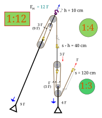
The same two pulley blocks due to modified installation but now 1:12
(with a different pulling direction)


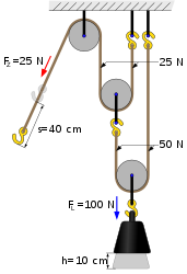
With the power pulley system, the power saving is achieved exclusively by means of loose pulleys: the rope of each pulley is attached to the support and the next pulley. While the full weight force still acts on the lower loose pulley, this is already halved on the lower rope, so that only half the force is applied to the upper loose pulley. The force is halved again on this role. The tensile force, which is deflected downwards by a fixed roller, acts on the rope of the last roller. This increases the effect with the number of loose roles:
- .

Differential pulley block


The differential pulley block consists of two fixed rollers that are firmly connected to each other and have different diameters . The load is hanging on a loose pulley. This type of pulley system uses a continuous (i.e., connected at the ends) rope in which the tension is not the same everywhere. The rope is fed back from the larger pulley to the load and on the other side via the smaller pulley. When you pull it up, the rope winds up on and off the larger roll. With one turn, the length of the rope loop on which the weight is attached is shorter by the difference between the two pulley circumferences. Because of the loop, the weight is only raised by half of this distance using the pulley principle. In addition, the force that is required for one revolution of the rollers is determined by the circumference of the larger roller. This circumference corresponds precisely to the pulling distance of the rope for one revolution, over which the work is then distributed. This gives the force:
- .
- (R = radius of the big roll; r = radius of the small roll)

An important advantage of this type of pulley system is the material and weight savings. Due to the circumferential rope, its length is almost independent of the transmission ratio of the pulley. Furthermore, only three roles are required. Since a (non-slip) firm contact between rope and pulley is required for this function, a chain is often used in a differential block and tackle instead of the rope and a chain wheel is used instead of the pulley .
If a differential winch with the crank length K is used instead (see figure, R and r are still the radii of the rollers), the formula is:
- .

Münchhausen technology

The Münchhausentechnik is suitable for self-rescue if, for example, the preceding mountain guide falls into a crevice and the partner does not master any rescue techniques. A variant of the Münchhausen technology consists in the use of a pulley system as a self-winding mechanism. The distribution of forces is to be calculated differently than with the usual pulley system. The climber who has fallen and is hanging on the rope (F L = load) pulls himself up using two pulleys (alternatively with two guide carabiners) on the pulling rope. The simple pulley system now carries the climber with three strands of rope, whereby the pulling weight (F Z ) on the pulling rope is reduced to 1/3 of the weight. Thus, neglecting friction, the transmission ratio is 1: 3.
Pulley without bottles or rollers
Swiss pulley
A Swiss pulley is a method of column rescue in case of accidents at glacial using a combined potency and factors pulley. The rope is diverted directly over the carabiners, as there are usually no pulleys available for such an aid measure.
Ellington pulley

The Ellington pulley system (named after its inventor) usually consists of two carabiners through which a strap is looped several times. The overlapping wraps turn the tape into “replacement rolls”. When tensioning, the lowest (inner) tape layer is pulled and the layers above move parallel to it. However, the high friction of the band on the carabiner only results in poor efficiency.
Laces
Lacing, for example on corsets or shoes, also use a rollerless pulling technique. Here the eyes, hooks or holes replace the roles. The large number of feedthroughs increases the friction and worsens the efficiency, but a reinforcing tensile or tensioning effect can still be achieved on a broad basis.
Reversion of the pulley blocks
Specialized pulley blocks also use a reversal of the pulling function of a pulley block.
- In clocks with weight drive, the drive weight often hangs on a loose roller; occasionally also on the bottom block of a pulley to increase the running time of the watch.
- The aircraft carrier USS Hornet (1943-1970) used a steam-powered catapult , which pushed apart a factor pulley system by means of a pressure cylinder. The towing rope that was driven in this way pulled a slide over pulleys, which accelerated the aircraft.
- Elevators with an indirect hydraulic elevator use the same function to move an elevator with a short stroke.
- A reverse power pulley accelerates the pulling rope.
-
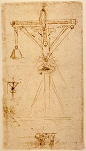
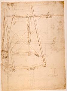
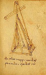
Mechatronic presses advantageously use the pulley principle, based on Leonardo Da Vinci's drawing 500 years ago.
 Drawing by Leonardo Da Vinci with 20 scrolls

Lifting heights of different designs

The arrangement of the rollers or the type of pulley system also plays a decisive role in the maximum reachable lifting position. While the rollers arranged one above the other represent the longest design (proper length), the arrangement on an axis next to one another can shorten the overall length. One of the shortest versions of a pulley block is the Ellington pulley block.
Backflow protection


When moving loads, it may be necessary to temporarily secure or fix the load at a certain height. The return protection required for this is available with various aids. On the one hand, there are already built-in anti-return devices on some pulley blocks, which block the rope with eccentric clamps. Furthermore, additional parts to be added on or built in are useful and are pushed in either by hand or automatically. Examples Garda terminal , Kara-eight loop , split tail , ascender , Tibloc and Tube to name just a few.
Some of these clamping devices have a blocking effect in one direction and cannot automatically loosen, for example to enable the load to be lowered.
However, this can be achieved through various combinations. The Bachmann clamping knot can be loosened on the pulled carabiner (in the picture on the left: using the blue “rip cord”). The Blake knot can also be loosened with a looped “rip cord” (picture on the right: blue cord → to the bottom right). In this way, a pulley block can be fixed and loosened from a distance (e.g. from a standing position on the floor) and thus operated by lowering it again.
Friction loss and efficiency
All of the above equations only apply provided that there are no losses due to friction. In practice, however, the friction losses of the deflection pulleys themselves and the rope on the deflection pulleys should not be underestimated. The rope, the movable pulleys and the lower suspension also have a not inconsiderable mass, which increases with each new roller. The tensile force is in practice, therefore, in any case greater than calculated theoretically: . For the efficiency of a pulley applies: .


literature
- M. Oppolzer, T. Wahls: I Like To Move It. Pulley blocks in rope technology. Hamburg 2019, ISBN 978-3-9820618-0-1 .
- Rescue Technician: Operational Readiness for Rescue Providers. St. Louis, Missouri 1998, ISBN 0-8151-8390-9 .
Web links
- Collection of materials and tasks on LEIFIphysics
- Relaxed on tension - pulley blocks in tree care
- Pulley without bottles , PDF of the University of Münster
- Leonardo's pulley study with 20 rollers (Codex Forster III)
supporting documents
- ↑ The simple machines (Deutsches Museum) (PDF; 1.3 MB)
- ↑ Plutarch : Bíoi parálleloi, Marcellus 14.8 ( English translation. Thayer, Loeb 1917 ); see. Polybios , Historíai 8, 5-7 ( English transl. Thayer, Loeb 1922ff ). reported that Archimedes is said to have pulled a loaded warship from the king's arsenal using pulleys and his own physical strength.
- ↑ GEOEPOCHE No. 76, page 139
- ↑ Crane picture with pulley by Leonardo Movable pulley on crane
- ↑ Pulley study of Leonardo Leonardo's "lifting machine"
- ↑ Leonardo's pulley system (with picture) ( Memento from January 25, 2013 in the Internet Archive )
- ^ Transport and erection ( Memento from May 1, 2010 in the Internet Archive )
- ^ Moving the Vatican Obelisk
- ↑ Arrangement of the pulleys on the floor
- ↑ The sky is the limit: human powered cranes and lifting devices (... The obelisk was raised using a wooden lifting tower 27.3 meters tall, ropes up to 220 meters long, 40 capstans, 800 men and 140 horses ...) different quantities
- ↑ Arrangement of the 40 capstan systems around the obelisk , image: arrangement of the pulleys
- ↑ Picture with different blocks with up to 6 rolls each (around 1600) Picture: Arrangement of the blocks on the obelisk
- ↑ Ellington pulley system (picture)
- ↑ The Münchhausentechnik - The Baron of Lies as mountain rescuer (PDF; 753 kB)
- ↑ The second variant consists of the Prusik technique with climbing loop and Prusik knot
- ↑ “One-sided pulley system” (lacing) on an orthopedic corset ( memento of the original from February 21, 2014 in the Internet Archive ) Info: The archive link was inserted automatically and has not yet been checked. Please check the original and archive link according to the instructions and then remove this notice.
- ↑ pulley block without rollers; Principles, models etc. ABoK # 3118 - 3121, same as # 3260 - 3266
- ↑ Source: HISTORIC AMERICAN ENGINEERING RECORD, USS HORNET (CVS 12) -PDF file ( Memento of the original from February 22, 2014 in the Internet Archive ) Info: The archive link was inserted automatically and has not yet been checked. Please check the original and archive link according to the instructions and then remove this notice. , Sketch with description of the catapult below deck , photo of the “catapult ropes” ( memento of the original from February 22, 2014 in the Internet Archive ) Info: The archive link was inserted automatically and has not yet been checked. Please check the original and archive link according to the instructions and then remove this notice.
- ^ Meyers Großes Konversations-Lexikon (8.) Indirect hydraulic elevator
- ↑ water scooping a pulley device by means of pumping station . April 12, 2013. Archived from the original on April 12, 2013.
- ↑ Patent description: press with pulley principle (drawing)
- ^ A clever solution, by Heinz Prohaska
- ↑ As early as 1862, lowering / braking of loads on pulley blocks was introduced. Braking pulley from Meunier in Paris Google Books: Peter Rittinger, The general industrial exhibition in London in 1862 Hof und Staatsdruckerei Wien, 1862. p. 14