Computer-aided architectural modeling
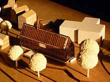
Computer-aided architectural modeling (CAAM) is the computer-aided manufacturing process for architectural models .
description
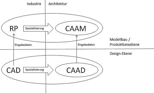
Based on 2D or 3D input files of the computer-aided architectural design ( CAAD ) process, CAAM mainly uses rapid prototyping (RP) technologies and machines to produce architectural models with a variety of materials with high precision. Similar to the specialization of CAAD from Computer Aided Design (CAD) in the architectural design area, CAAM developed from Rapid Prototyping (RP) in the architectural model making area.
The following diagram shows the relationships between RP / CAAM and CAD / CAAD:
history
About 15 years ago (1997), architecture in rapid prototyping technologies discovered ways to increase precision in architectural model making. Up until then, architectural models had been created very time-consuming by hand, mainly by architecture model builders.
The introduction of CAAM enables architects and students to create models much faster and with high precision, from the draft model to the presentation model.
CAAM has also become more and more important in architecture studies in recent years. It will not completely replace manual architectural model making. However, due to its increasing simplicity and improved accessibility, even for small businesses and individuals, CAAM has the potential to revolutionize architectural model making.
Technologies
Rapid prototyping machines are very interesting for architectural model making because of their independence from certain shapes and the possibility of creating all kinds of individual pieces on the basis of Computer Aided Architectural Design (CAAD) input files. They are only limited by their installation space.
2D laser cutting
Laser cutting machines can cut or engrave plates of various types and materials:
- Paper and cardboard
- Rigid foam panels
- Wood
- metal
- Acrylic glass and other plastics with a high melting point
- Ureol
- stone
RP machines for CAAM can cut materials with an approximate thickness between> 0 and 2 cm, depending on the material type. All materials can be engraved with an approximate thickness between> 0 and 0.5 cm, depending on the material type and thickness.
Laser cutting machines are ideal for the production of geometric, sharp-edged 2D shapes, which are the components for complex 3D building models. They are also very well suited for the production of 2D free forms as components of 3D layer models such as B. Landscapes.
Preparation of input files for 2D laser cutting:
2D laser cutting input files consist of 2D vector data. They can be created with all vector-based graphics programs, e.g. B. with AutoCAD, Rhinoceros, Allplan, Vectorworks, ArchiCAD or Illustrator.
The laser cutting machines distinguish vector data based on their color, not on properties such as thickness. The colors define the cutting sequence, e.g. B .:
- First engrave the window frame in a facade (color 1 - red),
- then cut out the window areas (color 2 - blue),
- and finally cut out the facade outline (color 3 - cyan).
Only pixel data are required for 2D engraving. They can be created with any program that can process pixel data, i. H. not only the above Graphics programs, but also simple graphics programs like Paint and Photoshop.
3D CNC milling
3D CNC - milling machines remove material with a milling drill. You can produce complex surface geometries in one piece with high precision (± 0.05 mm), perfect for curved freeform geometries. These machines can mill blocks of material of different types:
- Wood
- Ureol and other rigid foam blocks
- resin
- metal
- Plastic materials such as acrylic glass, fiberglass and polystyrene
- stone
Milling machines with 3 axes can mill objects with dimensions up to 2 × 3 m, but only up to a height of approx. 13 cm. Milling machines with more than 3 (up to 7) axes have a limited installation space, mostly up to 50 × 50 × 50 cm because of the surrounding arms, but are able to create surfaces that are curved inward.
Preparation of input files for 3D milling:
Input files for 3D milling can be created with programs that are capable of designing 3D objects. Main programs for this purpose are Rhinoceros, AutoCAD and ArchiCAD. The 3D files must be exported in one of the following file formats in order to be recognized by the milling machines: .stl, .vrml, .iges
All milling machines can read one or more volumes at the same time, but only closed volumes, even if they are positioned (directly) next to each other or overlapping.
The above guidelines for preparing input files also apply to all other 3D RP technologies such as 3D printing , 3D laser sintering and stereolithography .
Stereolithography
Stereolithography machines use a laser beam to cure a liquid polymer from layer to layer. You can create complex volumes and enclosed interiors. These machines can harden the following liquid materials:
- Polypropylene (PP), white
- USK Solid Gray 3000 (very hard)
- Flex 70B (rubber-like)
- Xtreme (resin)
- Nano Tool (heat-resistant, very thin structures possible)
The installation space dimensions of stereolithography machines are standard 50 × 50 × 40 cm (L × W × H), up to 210 × 70 × 80 cm. In order to realize free-floating geometries, support material is required. After fabrication, the only rework necessary is to remove the support material (if any).
3D printing with powder layers
3D printing machines create a powder layer and then print a powder adhesive onto this layer according to the object geometry. This process is repeated from layer to layer. You can also create volumes within volumes. Powder material based on plastic or plaster of paris can be used as material, each with a special adhesive. Support material is not required as the geometry is completely enclosed by the powder, which can thus serve as support material wherever necessary.
The installation space dimensions of these machines are as standard 15 × 15 × 15 cm (L × W × H) up to 25 × 25 × 30 cm. The powder layer thickness is between 0.17 mm and 0.25 mm.
After manufacturing, it is highly recommended to soak the objects in resin or brine to make them more resistant.
3D printing with powder layers is the only technology that can immediately create objects in any color (comparable to a "normal" CMYK color printer) by coloring the printer adhesive.
3D printing using the plastic melt process
3D printing machines create the object by melting plastic from layer to layer. You can also create volumes within volumes. These machines can use Poly Lactic Acid (PLA) or Acrylonitrile Butadiene Styrene (ABS) plastic materials in various individual colors to build the objects.
In order to realize free-floating geometries, support material is necessary, which can then either be dissolved or broken off, depending on the object geometry.
The installation space dimensions of these machines are as standard 15 × 15 × 15 cm (L × W × H) up to 25 × 25 × 30 cm. The plastic layer thickness is between 0.17 mm and 0.25 mm.
After fabrication, the only rework necessary is to remove the support material (if any).
3D laser sintering
3D laser sintering machines first create a powder layer. The object geometry is then "baked together" in this layer with a laser beam. This process is repeated from layer to layer. Volumes can also be created within Volume. The machines use different plastic or metal materials:
- Polyamides (black, gray, white) and elastomers (black, white)
- MaragingSteel, CobaltChrome, StainlessSteel (extremely expensive)
Support material is not required as the geometry is completely enclosed by the powder, which can thus serve as support material wherever necessary.
The installation space dimensions of these machines are as standard 15 × 15 × 15 cm (L × W × H) up to 25 × 25 × 30 cm. The powder layer thickness is between 0.1 mm and 0.2 mm. The powder particle size is 50 µm.
No reworking is necessary due to the very hard material.
See also
- model
- Modelling
- Architectural model
- Architectural representation
- Portal: architecture and construction
Web links
- EUROMOLD : World trade fair for tool and mold making, design and product development


