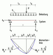
Single span
The single-span beam or beam on two supports is the simplest static element. It is the basic element of many bridges and buildings and is often used as an exercise in technical mechanics .
The carrier is statically determined . Under load, three support reactions occur in the two camps . The support forces can be determined without complex calculation procedures.
External forces
Support reactions
| vertical support reaction in support A (fixed bearing; spherical bearing) | |
| horizontal support reaction in support A | |
| vertical support reaction in support B (floating bearing; roller bearing) | |
| horizontal support reaction in support B (disappears, since it is moveable without friction) |
Loads
| external forces , etc. | |
| external moments , etc. | |
| Line load |
Internal forces (internal forces)
| Normal force in the beam | |
| Shear force in the beam | |
| Moment in the bar |
Equilibrium conditions
All external loads and all support forces are in equilibrium .
- Sum of all vertical forces: z. B.
- Sum of all horizontal forces: z. B.
- Sum of all moments: z. B.
In the three formulas, three unknowns are included , , , according to the mathematical rules are solved. However, the signs must be strictly observed. Here and in the sketch above are positive: vertical forces from top to bottom, horizontal forces from left to right, right-turning moments.
Maximum bending moment with uniform load
The maximum bending moment of a single-span beam with uniform load results:
| maximum bending moment in the center of the span [kNm] | |
| Line load [kN / m] | |
| Span of the beam [m] |
With this formula, many other static systems can also be calculated to a good approximation (on the safe side). It is therefore often used for rough calculations without EDP support. For the articulated single-span girder with uniform load, however, the formula is an exact solution. The line of moments always forms a parabola .
Derivation:
The sum formulas for horizontal and vertical forces result in the following:
The x-axis is assumed in this case from the left and starting in A:
The maximum torque is always at the point where the first derivative of the torque line is zero. The first derivative of M (x) with respect to x gives the following formula:
Setting the formula to zero results in an x-value for the location of the local maximum:
Substituting this value in M (x) one obtains:
Parabolic stitch
The above formula can also be used to determine the parabolic stitch if, in addition to a uniform load, individual loads also occur (kink in the moment line).
See also
literature
- A. Goris (Ed.): Schneider construction tables for engineers . 20th edition. Werner Verlag, Cologne 2012, ISBN 978-3-8041-5251-9 , pp. 4.2 ff .


