Single-phase three-wire network
A single-phase three-wire network ( English split-phase electric power ) is a power supply system that is commonly used in North America for single-family households and small businesses (up to about 100 kW ). It is the alternating current version of Edison's now historical three-wire direct voltage system . Since there is voltage on two conductors, it is often erroneously referred to as a “ two-phase current system”. In fact, however, only alternating voltages in opposite phase (180 ° to one another) are applied to both conductors .
connections
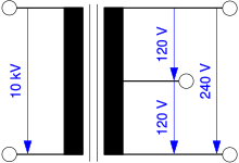
A transformer that feeds a single-phase three-wire network has a primary winding on the high-voltage side for the phase-to-phase voltage from the medium-voltage network , which is operated at 10 kV, for example. In star-shaped medium-voltage networks with a grounded star point, as is common in North and Central America such as the USA, the primary winding is connected between an outer conductor and the grounded star point. In triangular medium-voltage networks without an operationally earthed star point, as is common in Great Britain , the primary side is connected between two external conductors.
In rural, extensive supply areas, especially in Australia, New Zealand and Canada, single-phase three-wire networks on the high-voltage side are only supplied single-pole from the medium-voltage network for cost reasons. The earthing serves as the operational return conductor on the high-voltage side. These systems are called Single-Wire Earth Return (SWER).
On the secondary side, the transformer is designed so that between the neutral conductor (N) and any of the other two conductors, L 1 or L 2 , for example 120 V alternating voltage is applied. This voltage is common in the United States and Canada. Twice the voltage, i.e. 240 V, is applied between the two conductors L 1 and L 2 . The center tap on the secondary side is usually earthed. This is also necessary to enable the operation of residual current circuit breakers .
In rural areas of the UK, 230V / 460V, single phase, three wire networks are used to connect farms and a small number of remote, related houses. However, the users of house connections to which only two external conductors of the medium-voltage network are routed, then no three-phase alternating current ("three-phase current") is available - the operation of three-phase asynchronous machines for agricultural machines, for example, is only possible with additional circuits such as the Steinmetz circuit or with a frequency converter possible.
In Germany and many other regions of Europe, where households were partly supplied with single-phase three-wire networks until the second half of the 20th century, it has been switched to the newer three-phase AC network as standard since the 1950s, so that single-phase Three-wire networks are largely unknown here today and can only be found in individual old installations that are subject to inventory protection .
Three phase expansion
An extension of the single-phase three-wire network for three-phase alternating current, which is common especially in North America, is the Delta 4-Wire , High Leg Delta or Red-Leg Delta system. This type of low-voltage supply is completely unusual in Europe.
This extension has the advantage that no changes are required for the single-phase three-wire connections in the 120 V / 240 V range that are common in America. A three-phase supply from the medium-voltage network is required to supply the local transformers.
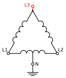
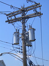
On the secondary side, the local transformer , which is connected as a three-phase transformer and in a triangle - in rural areas these are often three individual mast transformers instead - is connected as shown in the sketch opposite. The connections L 1 and L 2 and the grounded neutral conductor N are the connections corresponding to the single-phase three-wire system and are supplied by an external conductor. The additional fourth connection L 3 is referred to as a high leg and is supplied by the remaining two outer conductors. This results in a three-phase current of 240 V between L 1 , L 2 and L 3 , which can be used, for example, for three-phase asynchronous machines.
Since the earthed neutral conductor, in contrast to the systems commonly used in Europe such as the TT system, is not located at the star point , but at a center tap of one of the windings connected in a triangle, the voltages between the three outer conductors L 1 , L 2 and L 3 vary to the earthed neutral conductor N :
- L 1 to N = 120 V,
- L 2 to N = 120 V
- L 3 to N = 208 V ≈ 120 V √3
From the higher voltage of L 3 with respect to ground or N , the terms forwards High Leg from. To avoid connection errors and in accordance with Article 110.15 in NFPA 70 , this connection must be marked in orange or red. The US American NFPA 70, also known as the “National Electrical Code” (NEC), is roughly comparable to the DIN VDE standard ( VDE 0100 ) that is common in Germany in particular .
A disadvantage of the high-leg delta system as well as the single-phase three-wire network is that the outer conductors in the medium-voltage network are loaded very unevenly and this can lead to increased unbalanced loads . A distribution of the single-phase consumers to all three external conductors is not possible in this system on the low-voltage side and an unbalanced load can only be compensated for across several local transformer stations by alternately selecting the external conductors. Because of the unbalanced load, the transformers in North America are usually designed as three individual single-phase transformers with possibly different power and not combined into a single three-phase transformer with a smaller core cross-section for the same power.
literature
- Terrell Croft, Wilford Summers (ed): American Electricians' Handbook . 11th edition. McGraw Hill, New York 1987, ISBN 0-07-013932-6 , pp. 3-10, 3-14 to 3-22 .
See also
- Country overview connector types, line voltages and frequencies
- Autotransformer system , special version of the traction power supply
Individual evidence
- ↑ SWER, How does it work? ( Memento of the original from May 23, 2010 in the Internet Archive ) Info: The archive link was inserted automatically and has not yet been checked. Please check the original and archive link according to the instructions and then remove this notice. , RuralPower.org, (Eng.)
- ↑ Archive link ( Memento of the original from July 22, 2012 in the Internet Archive ) Info: The archive link was inserted automatically and has not yet been checked. Please check the original and archive link according to the instructions and then remove this notice. Siemens "Basic of Panelboards"


