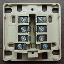
F-010
The F-010 telephone socket was the standard socket in France for subscriber lines . Because of its appearance, it is also referred to synonymously as a T-box. Outside France, you can still find them in the following countries: Algeria, Andorra, Bhutan, Burkina Faso, Chad, Comoros, Congo, Djibouti, Egypt, Equatorial Guinea, Gabon, Grenada, Ivory Coast, Madagascar, Mali, Mauritania, Mauritius, Monaco, Morocco, Niger , Rwanda, Somalia, Switzerland, Togo and Tunisia.
Until 2003, the F-010 socket was used as an approved telephone socket by France Télécom. It was used for all telecommunication devices such as telephone, fax, modem, etc. Her successor since then the registered jack RJ-41S in the execution 8P8C. The T-Box is under Spécifications techniques d'interface of France Telecom described.
Connection diagram
| Clamp | Pair | colour | meaning | Remarks |
|---|---|---|---|---|
| 1 | 1 |
|
a-core | |
| 2 | 1 |
|
a-wire for secondary alarm clock ( ringer secondary device ) | not used today due to DTMF |
| 3 | 1 |
|
b-core | |
| 4th | x |
|
unused |
possibly used for:
|
| 5 | x |
|
unused |
possibly used for:
|
| 6th | 2 |
|
a-core | |
| 7th | 2 |
|
a-wire for secondary alarm clock ( ringer secondary device ) | not used today due to DTMF |
| 8th | 2 |
|
b-core |
Note: Many telephone plugs only have the first six terminals.
Tensions
A nominal 54 V DC voltage is applied between La and Lb, 48 V is common in telephone systems. The ringing voltage is nominally 70 V AC (50 Hz) and is superimposed on the operating voltage. In fact, the permissible working range for the ringing voltage is 25 to 100 V.
Test module
The test module (also called the RC module) is used to test the telephone line on the socket inlet side. It consists of a resistor of 20 kΩ and a capacitor with 2.2 µF. This RC circuit connects wires a and b, with the capacitor on terminal a. There are the following versions:
- Module with three connections (for line 1, terminals 1 and 5 are then connected)
- Module in which terminals 4 and 6 are connected in series and in which there is a connection between terminals 1 and 3 when the telephone plug is not inserted.
Individual evidence
- ↑ France Télécom, Interface d'abonné analogique (PDF; 673 kB) , STI 1, édition 8.
- ^ Module d'essai, Module d'essai
- ↑ S63, reproduction de l'étiquette


