Communication diagram (UML)
| Structure diagrams of the UML |
|---|
| Class diagram |
| Component diagram |
| Composition structure diagram |
| Object diagram |
| Package diagram |
| Profile diagram |
| Distribution diagram |
| UML behavioral diagrams |
| Activity diagram |
| Use case diagram |
| Interaction overview diagram |
| Communication diagram |
| Sequence diagram |
| Timing diagram |
| State diagram |
Communication diagram (Engl. Communication diagram in) is called Unified Modeling Language (UML) a behavior chart illustrating the exchange of messages.
In older versions of UML diagrams were such as collaboration diagram (Engl. Collaboration diagram ) refers.
Notation of lifelines and messages
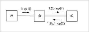
The figure on the left shows an example of a communication diagram with a header and a content area. The optional keyword in the header is in a communication diagram as in any interaction diagram sdor interaction.
Similar to a sequence diagram , lifelines are shown as rectangles in a communication diagram. Calling this symbol “lifeline” may seem a bit strange, because in contrast to the sequence diagram, the dashed line that represents the time axis for exchanging messages is not displayed in the communication diagram. A message is drawn as a short arrow. The direction of the arrow points from the sender to the recipient of the message. The arrow is labeled with a sequence number and a signature of the message, for example the signature of the operation if the message is a synchronous call to an operation.
Every connection in the communication diagram must be matched by an association in the class diagram .
Temporal order of the messages
The time sequence of messages is modeled in communication diagrams with sequence expressions. A sequence expression is assigned to each modeled message, from which it can be seen what the previous messages are and which messages run in parallel.
A sequence expression consists of a sequence of sequence terms separated by a period (.) , Followed by a colon (:). Sequence terms are numbers, for example 1, 10or 22, optionally followed by a lowercase letter, for example aor b. The following strings are therefore valid sequence expressions: 1, 1.7, 1a.6, 1a.6c.2.
The meaning of sequence expressions is given by three rules:
First, the sequence of terms in the sequence expression indicates the level of nesting in a message. A message with the sequence 1.2b.1expression is therefore sent by an occurrence after it has received a message with the sequence expression 1.2b. In the figure on the right, the message with the sequence expression follows the message with the sequence 1.2b.1expression 1.2b, which in turn follows the message with the sequence expression 1.
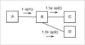
Second, purely numeric terms indicate a sequential order at the same level of nesting. The figure on the right shows an interaction in which the lifeline sends :Bthe message with the sequence expression 1.1before the message with the sequence 1.2expression.
Thirdly, terms with a letter at the end indicate messages that are sent in parallel. In the diagram on the right, you can see that the message with the sequence printout 1.1aand the message with the sequence 1.1bprintout are sent at the same time.
literature
- Christoph Kecher: UML 2.0 - The comprehensive manual Galileo Computing, 2006, ISBN 3-89842-738-2
- Heide Balzert: Textbook of Object Modeling - Analysis and Design with UML 2 Elsevier Spectrum Akademischer Verlag, 2005, ISBN 3-8274-1162-9


