
Use case diagram
| Structure diagrams of the UML |
|---|
| Class diagram |
| Component diagram |
| Composition structure diagram |
| Object diagram |
| Package diagram |
| Profile diagram |
| Distribution diagram |
| UML behavioral diagrams |
| Activity diagram |
| Use case diagram |
| Interaction overview diagram |
| Communication diagram |
| Sequence diagram |
| Timing diagram |
| State diagram |
A use case diagram (. Engl use case diagram ), also Nutzfalldiagramm , is one of the types of diagrams of the Unified Modeling Language (UML), a language for the modeling of the structures and the behavior of software - and other systems. It depicts use cases and actors with their respective dependencies and relationships .
The use case diagram has been a behavior diagram since UML 2 . It represents the expected behavior of a system and is therefore used to specify the requirements for a system.
A use case diagram does not represent a process description. Instead, it can be represented with an activity , sequence or collaboration diagram (from UML 2.x communication diagram).
Use case diagram in bullet points
- The aim is to show as simply as possible what you want to do with the software system to be built and which cases of application exist.
- Actors are represented as " stick figures ", which can represent both people such as customers or administrators and a system (a ribbon symbol is sometimes used in systems).
- Use cases are shown in ellipses. They must be described (e.g. in a comment or a separate file).
- Associations between actors and use cases must be indicated by lines.
- System boundaries are indicated by rectangles.
- Include relationships are marked with a dashed line (marked with <<include>> ) and an arrow to the included use case, which is necessary for the calling use case.
- extend relationships are identified by a dashed line (marked with <<extend>> ) and an arrow from the extending use case, whereby this can be activated by the calling use case , but does not have to.
elements
The system context is marked by system boundaries in the form of rectangles.

Actors are represented as "stick figures", which can represent both persons such as customers or administrators as well as a system.
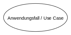
Use cases are shown in ellipses. They must be described (e.g. in a comment or a separate file).


Relationships

Association / communication of actor and use case.

Multiplicity of actor and use case, whereby the default setting of the actor is 1.
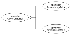
Generalization of use cases.

Generalization of actors.

Include relationship in the use case diagram, where use case A includes use case B.
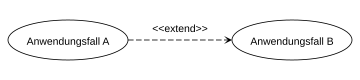
Extend relationship in the use case diagram, where use case A extends use case B.

Extend relationship with extension point, where use case A extends use case B under the specified condition.
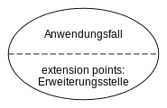
Use case with extension point.


Examples
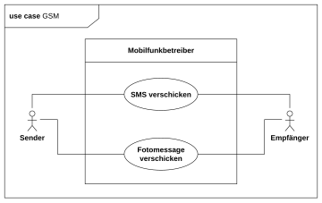
The keyword in the header is use case . The use case diagram in the figure on the left is separated into a header and a content area and enclosed with a frame, as the UML2 provides for all diagrams.

A more complex use case diagram that captures the relationships between the actor
Benutzerand the systemMultimediasystem. A user is interested in four use cases, which in turn are related to each other.Musik-CD erstellenis the most complex use case because it imports two other use cases and is optionally extended by a thirdCD beschriften,,.


Differences to UML 1.x
The use case diagram is now classified in UML2 as a behavior diagram and no longer as a structure diagram. Furthermore, actors must now have a name and the preconditions of the respective extension points must be attached to the corresponding extension relationship by means of a note.
See also
literature
- Bernd Oestereich : Analysis and Design with UML 2 , Oldenbourg Wissenschaftsverlag, 2006, ISBN 3-486-57926-6
- Christoph Kecher: UML 2.0 - The Comprehensive Manual , Galileo Computing, 2006, ISBN 3-89842-738-2