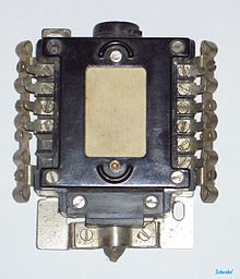
Solder lug


A Tab , (Engl. Solder lug ) is a member, with which one wire or strand can attach electrically conductive. Solder lugs are positively attached or pressed in on a base plate or solder lug strips, or they can be screwed or riveted. Similar components are solder terminals , solder strips and solder pins .
Soldering lugs were for a long time one of the most important connecting elements during the development of electronics, but they have been replaced in many areas of application by the development of printed circuits (circuit boards).
To create a conductive connection, the soldering lug is first mechanically cleaned and then tinned. Tin-plated solder lugs are also commercially available. One or more wires can be soldered to a soldering lug. There are soldering lugs with one or more soldering lugs (single and multi-pole soldering lugs).
Copper or brass , for example, are used as materials .
function
Soldering lugs are used for the mechanical stability of the connections between components and between components or components and lines. They also ensure the electrical connection. In particular for the connection of cable harnesses, but also as a basis for the circuit structure, there were solder lug strips and solder lug pillars. The connections of tube sockets, potentiometers, variable capacitors , switches and block capacitors combined the function of making connections with the function of supporting the fastening of components or cables. Transformers that are not soldered onto printed circuit boards often have solder lugs, whereby the primary and secondary connections have often been separated.
In principle, a maximum of three wires should be connected to each solder lug, which results in a total of six with the usual tubular rivet design with two lugs.
In addition to the soldered connection, the connection should also be form-fitting. That means that the wires should be put through the hole of the eyelet. The reverse type of connection consisted of soldering pins around which the wires and the connecting wires of the components were looped around. In some cases, several turns were wound before soldering.
Soldering lugs must not be subjected to excessive mechanical loads. Heavier components cannot be attached directly to them. They are fixed, for example screwed, to the base plate. Longer wires need a fixation and possibly a strain relief.
predecessor
As far as one can speak of predecessors, there were conductor tracks riveted to hard paper or hard plastic with contact springs that carried the components. The contact springs and the rivets thus had a function comparable to that of the soldering lugs.
Solder lugs and printed circuits
Printed circuits are limited in terms of the frequency of soldering. It is therefore common to provide soldering lugs or soldering terminals for those components whose specific value must be selected during calibration (e.g. so-called asterisk resistances). Lines were also connected to such support points during the installation of the equipment.
In contrast to the previously mentioned soldering lugs, the soldering terminals are usually intended for the connection of only one wire. Designs also differ with regard to the diameter of the wire to be connected.
There were flat solder lugs, the lower end of which was shaped like a sword, and hollow rivet-like solder lugs with a round base and bulge for the component side of the circuit board. Insofar as the hollow rivet-like components did not have a side hole and were intended for introduction from above, they were also referred to as solder pins.
In the case of multi-layer circuit boards, the connections between the layers are made either by pieces of wire or by plated-through holes. With frequent adjustment of components (potentiometers), the circuit boards were so stressed by pulling them out and plugging them into so-called adapter cards that through-contacts tended to fail and thus impaired stable operation.
Solder lugs in components or components
Soldering lugs are also used in the sockets of electronic components, for example in rotary capacitors or potentiometers. Further applications are connections of connectors and cable lugs , connections on printed circuit boards for soldering wires and quickly built prototype circuits.
Alternatives
Square cross-section pins have been used for coiled connections in which the wires are wrapped around the pin in several turns with the aid of a winding gun.
Plug connections are often used to connect assemblies.
Some components have soldering lugs as connections. In other cases, solder pins or solder terminals are used.
presentation
The soldering lugs are not shown in circuit diagrams, but in the wiring diagram, on assembly plans and in parts lists.
See also
literature
- Reinard J. Klein Wassink: Soft soldering in electronics . 2nd Edition. Eugen G. Leuze, Saulgau 1991, ISBN 3-87480-066-0 .
- Wolfgang Scheel (Hrsg.): Assembly technology of electronics . Verlag Technik u. a., Berlin a. a. 1997, ISBN 3-341-01100-5 .


