Winding connection
The term winding connection or winding technique (also wire-wrap joint , wire wrapping ; Engl. Wire-wrap connection or wrapped joint ) denotes an electric connection technology by means of cold welding , the u. a. is used in electronic assemblies, mainly in the field of telecommunications technology in the field of telephone systems . Until the beginning of the 1990s, winding technology, like threading technology , was also used to set up electronic circuits such as computer systems and for prototypes of single-board computers - in this area it was largely replaced by soldered circuit boards and SMD components due to the unfavorable high-frequency properties at high clock frequencies .
General
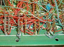
A single core made of solid wire (conductor diameter between 0.2 and 0.8 mm) is wound around a sharp-edged winding pin with a square or rectangular cross-section using a mostly motor-driven winding mandrel (electric hand tool, winding gun ) . The high clamping pressure to the pin edges by cold welding for oxide-free , gas-tight contact points. At least four turns are required for a perfect connection. The usual pin cross-section is 0.6 × 0.6 mm to 1 × 1 mm. The pin length is usually measured for two to three coils (i.e. two to three cores) one above the other and is up to 50 mm. It is usual that two turns of insulated wire are wound around the pin at the beginning before the bare copper comes. This should ensure that mechanical vibrations are cushioned and the wire does not break when exposed to vibrations.
The connection can practically only be loosened again with the de-wiring tool (a special mandrel with a hollow claw or hollow helix) because the wire is micro-welded and work-hardened. The post is no longer so sharp-edged after loosening, so that a new connection on this post is no longer so reliable. Although the unwound wire can be rewound on another post after straightening the core , the wire is now at risk of breaking due to the strain hardening caused by double deformation. These connections are therefore less reliable.
Application examples

The winding connection technology was introduced in Germany in 1973 at what was then the Deutsche Bundespost (DBP) in order to establish connections at the distributor of LF amplifier points and 2 Mbit distributors. With a special winding gun, the wires were cut to the correct length, stripped and applied to the connection pin with a wire coil without soldering. The determination of the correct winding insert for the existing wire thickness is based on the designation AWG ( American Wire Gauge ), e.g. B. AWG 26 made.
This technology is still in use (as of 2011) in older exchanges from the 1990s, but is being replaced by LSA technology as part of new construction measures and shutdowns, as far as 2 Mbit connections are concerned .
The control computers of the Apollo program ( Apollo Guidance Computer ) were manufactured using winding connection technology, which were then encapsulated with epoxy resin. The reason was the significantly higher reliability compared to soldering.
Winding technology was also used for the rear wiring of the backplane of connectors for plug-in cards in devices and early computers. For this purpose, the pins of the connector protrude from the back of the carrier board and can be wired individually. Other connections (e.g. operating voltages), on the other hand, are already implemented as conductor tracks.
Another application is the production of prototypes .
Today, winding technology is mainly used for wiring spring-pin adapters for in-circuit tests , and occasionally for user-specific device configurations.
Advantages and disadvantages
This process achieved considerable advantages over conventional cabling: soldering was no longer necessary, instead of prefabricated cables, wire could simply be taken from the reel, and a significantly higher packing density was achieved on the distributor, so that it could now be made smaller and more cost-effective.
Winding with a pistol is faster than soldering and also much more reliable: the problem of cold soldered joints is eliminated, as is the risk of damaging the insulating material of neighboring wires from the effects of heat.
Disadvantages are the lack of automation and thus the great amount of manual labor, as well as the above-mentioned mechanical unreliability of both the wire and the post when changing a connection.
If there is moisture, crevice corrosion is sometimes observed after a few years and the cold welded joint corrodes. Contact resistance pin-wire over 100 ohms and interruptions were observed. Cleaning is useless in such cases. A repair is possible by manual soft soldering. Instead of measuring every point, all wraps can be re-soldered. With a large field, this means a lot of time, but then the connections are fine again.
This only applies to the application on circuit boards. In the event of a fault, telecommunications technology distributors are rewrapped. If there is no wire supply, a new wire is pulled in. Under no circumstances is soldering, as re-soldered connections cannot be switched.
Tools and details
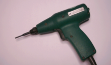
A fully automatic winding gun carries out all the necessary work: stripping, winding, cutting off the wire. There are also simple winding guns that only wind, but not strip the insulation and cut off after winding.
In addition to the winding gun, there are also hand winding mandrels. They are similar in shape to the machine inserts, but with a handle. The further development were mechanical winding tools without a motor, which are operated by means of a ratchet-like pistol grip and thus perform a rotary movement. The advantage of these tools is that they can be used in places without power. The disadvantage is that you have to shorten the wires to the correct length by hand and strip the insulation with the special tool.
The cable core is usually wound around the square pin in a clockwise direction. With the hand winding mandrel it is also possible to wind the wire the other way around the pin. Then it cannot be removed again with the unwrapper because it has incorporated a left-handed hollow helix or claw (not clearly visible in the picture.)
literature
- Paul Horowitz, Winfield Hill: The Art Of Electronics . 2nd Edition. Cambridge University Press, 1989, ISBN 0-521-37095-7 , Chapter 12.03 (English).
Web links
- Detailed description of the wire wrap technology (pdf, 314 kB, accessed on July 3, 2014)
- Practical information on wire wrap technology (pdf, 194 kB, accessed on July 3, 2014)


