
soldering

Soldering is a thermal process for the integral joining of materials, whereby a liquid phase is created by melting a solder (fusion soldering) or through diffusion at the interfaces (diffusion soldering) . A surface alloy is generated, but the workpiece is not melted in depth: the liquidus temperature of the base materials is not reached. After the solder has solidified, a material connection is established, as is the case with welding.
The difference to welding is that during welding the liquidus temperature of the components to be connected is considerably exceeded and that during soldering the chemical bond can be the same, but the liquidus temperature is hardly or not exceeded. The type of chemical composition of the connection differs depending on the tools used (welding wire for welding, solder paste or solder wire for soldering).
History of soldering
Soldering is a very old technique that has been proven to be around 5000 BC. BC and was probably known even before that. The metals gold , silver and copper , which were known at the time , were processed into cult or jewelry objects, with soldering being used as a connection technology. In so-called reaction soldering (or diffusion soldering), copper salts are reduced in the CO atmosphere of the charcoal fire, and the copper components result in a solderable alloy in the chemical reaction with gold or silver . The resulting eutectic has a lower melting point than the pure metals gold, silver and copper. Compared to the melting temperatures of gold (1063 ° C), silver (961 ° C) and copper (approx. 1100 ° C), an alloy 66.5% gold / (residual) copper has a melting point of 889 ° C. As a basis for the copper salt z. B. Copper carbonate in the form of pulverized malachite , as well as admixtures of alum and soda / soda binder mixtures as "glue" are used. Images in ancient Egyptian tombs show gold workers with blowpipes in front of a charcoal fire . It was not until later that the technology, which is better known today, was used to use an existing alloy as a solder addition. Examples of this art of soldering are u. a. the Egyptian gold mask of Tutankhamun , a golden dagger of the Sumerians , found in Ur in Chaldea on the banks of the Euphrates (2600 BC), or a gold necklace of the Etruscans (6th century BC).
links
Connecting materials
An easily meltable metal alloy, the solder, is usually used as the connecting material . With its help, a metallic connection between two metallic components is created.
Ceramic and glass components can be joined with glass solder or - if they have been metallized beforehand - with metal solder and metal parts. As an alternative to previous metallization, active soldering is also suitable, in which an active element is added to the solder or the joining partner is itself an active element alloy. Active metals can be titanium or indium, for example. At elevated temperatures, these are affinity for oxygen and react with the oxygen in the oxide ceramic during soldering.
Connection techniques
Soldering stands alongside other joining techniques , e.g. As the welding, the bonding or interlocking connections, such as rivets , crimping , shrinking or a pressing joints . Soldering is particularly used for electrical connections .
A characteristic of a soldered connection is the intermetallic connection . In this thin layer, the base material and the solder form an alloy and form a solid bond.
The presence of different metals and alloys on soldered connections has a disadvantageous effect. In the presence of an electrolyte (e.g. moisture), galvanic elements such as a local element are created , which can lead to increased corrosion .
Classification of soldering processes

The liquidus temperature of the solder is decisive for the classification:
- up to 450 ° C: soft soldering
- from 450 ° C: hard soldering
- over 900 ° C: high temperature soldering (in a vacuum or under protective gas ; see DIN 8505 part 2)
The application decides on the method used.
Brazed joints are generally less strong than welded joints , but almost always stronger than soft soldered joints.
Plumb bobs

Solders are used as the material for producing a soldered connection . Metal solders are mostly alloys that are in the form of solder wire or solder paste . They often already contain a flux , which is usually incorporated into hollow chambers in soft solders, and as an outer coating, usually colored for differentiation purposes, with hard solders.
After soldering, a residue of the flux often remains on the soldering point.
Vacuum connections (high vacuum systems or electron tubes ) or those with high purity requirements (e.g. assembly of semiconductor lasers ) must be made without flux, therefore require clean surfaces of the joining partners and must be carried out under protective gas or vacuum.
Metallized ceramic parts and stainless steels that are subject to high thermal loads are often soldered with silver solder .
Glass solder for soldering ceramics and glass is processed pasty, it consists of powder of a particularly low-melting glass and organic additives that set the pasty consistency. The organic substances evaporate or pyrolyze and burn completely during soldering.
For heat exchangers in the automotive industry, aluminum-silicon hard solders are mostly used. In mass production, adapted, expedient forms of Al-Si solders are often used, for example as plating or solder rings.
Flux
In order for the diffusion process described above to take place, all metal surfaces must be bare and thus free from oxides and contamination.
Almost without exception, soldering is carried out under the influence of air ( wave soldering generally in a nitrogen atmosphere). Even while the soldering point is being heated, the oxygen in the air promotes oxidation of the surfaces, which endangers reliable and thus successful soldering.
Therefore, in such cases, a flux is applied before the soldering process. The flux reduces (deoxidizes) the surface during soldering and is intended to prevent new oxide formation before and during the soldering process, which would otherwise greatly reduce the flow and wetting properties , and also to reduce the inclusion of foreign matter. Another effect is the reduction of the surface tension of the liquid solder.
The type of flux depends on the area of application. Many fluxes must be removed after soldering, otherwise they are corrosive .
In special cases or for reasons of cost in mass production, soldering is carried out without flux under protective gas or vacuum. The protective gas prevents oxidation and can also have a reducing effect on existing oxide layers.
Heat input
Heat is brought in by means of a soldering iron , the flame of a soldering torch , hot air , hot steam , thermal radiation , laser or induction , in some cases also by means of ultrasound, electron beam or an electric arc (arc brazing).
Soldering in electrical engineering / electronics


Soldering is most widespread in electrical engineering and electronics. The soldering is done almost exclusively with soft solder .
Only so - called acid - free fluxes , such as rosin, are normally used as flux in electronics . The term acid-free refers to the cooled solder joint. During soldering, the decomposition products of the acidic components of the flux play a decisive role in the quality of the soldered connection. Even non-acidic fluxes can therefore have a corrosive effect.
In the case of large-area soldering, the objects to be soldered are typically tinned with soft solder on the joining surface beforehand in order to keep the thermal loads on the surrounding components low. At the same time, this preliminary work promotes wetting.
In electrical engineering today, wave soldering , reflow soldering and soldering with hot air are mainly used on an industrial scale . In spite of numerous other connection techniques ( crimping , wire wrap , screw terminals , insulation displacement technology , terminals ), soldering is still very popular. The dimensions range from a few centimeters down to a few tenths of a millimeter (for SMD components such as resistors or semiconductors ).
Soldering process
- Dip soldering
- Wave soldering / wave soldering
- Reflow soldering
- Light soldering
- Inductive soldering
- Resistance soldering
- Cold soldering
- Vacuum brazing
- Hot air soldering
- Laser soldering
- Soldering with an open gas flame
- Diffusion soldering
- Amorphous solder foil
- Vapor phase soldering
- Ultrasonic soldering
Quality of soldering

The wetting is an important criterion for successful soldering. Only enough solder should be used at the soldering point so that the contour of the component connections remains visible in the solder. The angle between a drop of liquid solder and the base material is called the wetting angle . A wetting angle of 0 to 30 ° is classified as “completely to sufficiently wetted”, from 30 to 90 ° as “partially wetted” and over 90 ° as “not wetted”. In principle, the wetting angle should therefore be less than 30 °.
Another quality feature is the cleanliness of the soldering points, for example, no solder residue should be found outside the soldering points. The soldering points should be clean and even, this also applies to the vias.
Cold solder joint


A phenomenon that is particularly feared when soldering in the electronics sector is the so-called cold soldering point. With a cold solder joint, there is no material connection between the solder and the joint partner.
Cold solder joints are often difficult to see. In contrast to correct soldering points, they may look matt (lead-containing solders solidify with a high-gloss finish, lead-free solders are generally matt) or have a slightly lumpy surface. Furthermore, the lack of a meniscus of good wetting is an indication of a poor soldering point. The mechanical and electrical properties of a cold solder joint are poor. Cold solder joints are typical causes of reliability problems in electronic assemblies.
Cold solder joints can have many different causes:
- For manual soldering, a solder with a wide temperature range between the liquidus and solidus temperature was used. The solder is mushy within this temperature range; even slight vibrations favor the creation of a cold solder joint.
- For manual soldering, it is therefore advisable to use a solder in which both temperatures coincide, such as B. L-Sn63PbAg with 178 ° C solidus and liquidus temperature.
- The soldering temperature was too low - the soldering point was too cold - probably the namesake. There was no or no complete wetting.
- The soldering temperature was too high. The flux has decomposed too quickly or evaporated before a deoxidizing effect sets in. The high temperature leads to rapid oxidation of the areas to be joined.
- When a soldered joint was cooled, it was not ensured that the entire soldered area between the liquidus and solidus temperature would remain free of vibration.
- The surfaces to be wetted are no longer wettable due to oxidation or overlaying (growing through of the intermetallic phase), so that the solder is more of a form-fitting type of "clamping".
Cold solder joints often do not cause an electrical interruption immediately. A cold solder joint can only withstand low mechanical loads. Because of this, both small vibrations or shocks to the soldering point and expansion movements in components that heat up can contribute to malfunctions. Vibrations occur on conductor tracks, for example: At the beginning the conductor track or the connecting wire is still "firmly" enclosed in the cold solder joint, but soon the vibrations of the conductor wire can "knock in" a play within the solder joint, and the wire can then move inside of the solder joint. A relative movement can now occur within the contact point, small contact interruptions occur as a loose contact , and electric arcs (voltage flashovers) can also occur with higher electrical currents.
In electronic devices and assemblies, interruptions and uncertainties in contact lead to malfunctions. The possible arcs can cause burns within the solder joint. These areas are then covered with a layer of soot or oxide. This further worsens the electrical contact.
Finding cold soldering points is often difficult because mechanical movement may initially make contact again for some time. Localization can be facilitated by targeted vibrations or a cold spray . Several soldering points that appear unreliable may have to be re-soldered “on suspicion”.
Loosening electrical soldered connections

By re-heating and thus liquefying the solder, electrical soldered connections can be separated from one another. Nevertheless, the soldered connection is in principle one of the non-detachable connections because the material properties change and the soldering point itself is destroyed during desoldering. Mostly, however, the component and the pad of the printed circuit can be used again.
Loosening solder joints is sometimes necessary for repair and component replacement. There are sometimes special tools and aids for desoldering or soldering apart, such as the solder suction pump or the desoldering braid .
In the event of excessive heating during operation of a module, incorrect dimensioning or overloading can lead to an unintentional loosening of the solder joint. Some high-load resistors are provided with a spring-loaded solder joint. If the resistor heats up significantly due to a defect in the connected circuit ( short circuit ), the solder joint opens and interrupts the further flow of current.
Lead-free electronic solders

Because of the risk to health and the environment from the lead in electronic solders, it had to be replaced in the electronics sector in the EU by July 1, 2006 ( RoHS DIR 2002/95 / EC; electronic scrap directive WEEE DIR 2002/96 / EC). The use of lead and other heavy metals, such as cadmium and mercury, is prohibited in electrical and electronic equipment that will be placed on the market from July 1, 2006.
Alloys of the Sn / Ag , Sn / Cu or Sn / Ag / Cu group are used as a substitute . However, these usually have a less universal area of application and bring z. T. technical problems such as embrittlement and whisker formation with it. The most serious disadvantage of these new solders is the approx. 10 K to 30 K higher melting point. Especially when assembling or soldering assemblies with many different components, this increased thermal stress can bring some components very close to their load limit. Increased failures as a result of this manufacturing step are possible.
Other solders have a very low melting point, which harbors the risk of accidental melting or reduced service life. A melting point that is too low can also occur if the composition changes during repairs with conventional solder. Different solders have to be used for different purposes. Some of these are already well mastered technologically.
Soldiers containing lead may be used by private users, but since March 1, 2018, nobody in the EU has been allowed to give them to them. Commercial users are allowed to use them if a special application makes it necessary, for example for particularly reliable soldering of products in the medical field. As with most activities involving the hazardous substance lead, however, the employer must regularly take special protective measures.
Tin-silver and tin-copper alloys
To switch to lead-free soldered connections, a replacement of the usual Sn60Pb40 solders and the introduction of higher melting SnCu or SnAgCu solders are being tested. In addition to higher costs, up to a doubling for lead-free solders, there are also problems with the qualitative assessment of the “dull” solder joints when using silver-containing alloys. In addition to a new crucible and the entire crucible inventory, a longer preheating section is required. Furthermore, silver can dissolve both stainless steel and titanium. Coated steel is therefore used for the soldering pot and the soldering nozzles. However, this coating is sensitive to mechanical stress (drilling, scratching, hitting).
The entire thermal process window has become smaller: the temperature difference between the melting point of Sn 95.5 Ag 3.8 Cu 0.7 (217 ° C) and the working temperature of 260 ° C is only 43 K. For comparison, it is 37 (melting point 186) for Sn 63 Pb ° C and a working temperature of 250 ° C) 64 K. This can mean, for example, that in the case of multilayer boards, boards with heat sinks, transformers or other heat-extracting components, the solder already solidifies when it rises in the via before it reaches the top and contact is made . A way out is to increase the energy input during the preheating phase. Working with higher soldering temperatures (up to approx. 280 ° C) would increase the process window, but can lead to melting effects on small components with low heat capacity.
The use of nitrogen to avoid oxidation products makes sense. Another problem that has not yet been resolved is the formation of whiskers , which can lead to short circuits on printed circuit boards. Components with high working temperatures (computers, power amplifiers) are particularly at risk. Lead-free solder is therefore not permitted in safety-relevant areas.
Tin-bismuth solder and other alternatives
Tin- bismuth alloys are another alternative . At 139 ° C, the melting point of Sn42Bi is even lower than that of Sn60Pb at 183 ° C, which means that the thermal load on the components can be reduced. The disadvantage is that tin-bismuth solder, e.g. B. alloyed with lead when re-soldering lead-containing soldered joints, Rose's metal - a metal that melts below 100 ° C - results. Due to the cost, tin-bismuth alloys can only be used for niches. Furthermore, indium - containing lead-free solders u. a. listed with their liquidus and solidus temperatures.
Soldering pipes

Copper or stainless steel pipes are also often soldered. A large number of fittings, known as fittings , are available for connecting and changing the direction of gas or liquid lines .
Depending on the intended use, hard or soft soldering is prescribed, whereby, by definition , soft soldering takes place below 450 ° C and hard soldering takes place above 450 ° C, in which different solders and fluxes are also used.
Drinking water pipes made of copper must be soft-soldered up to DN 25 (CU 28 mm × 1.5 mm), from DN 32 (CU 35 mm × 1.5 mm) hard soldering is permitted (DN = nominal diameter). Soft soldering is permitted up to CU 108.
Gas, oil supply and heating lines with flow temperatures of over 110 ° C must always be brazed.
Lines for refrigerants, for example when installing direct evaporator heat pumps , must be brazed and free of scale ( copper oxide ). The formation of scale inside the pipe can be prevented with nitrogen , forming gas or denatured alcohol ( ethanol ).
The connection point between two components is referred to as a soldered seam , their graphic representation is regulated in DIN EN 22553. A distinction is essentially made between butt joint (face to face) and overlap (pipe in pipe or surface on surface) as seam forms. The joining surface should be dimensioned as large as possible in order to be able to transfer forces well.
Arc soldering

Arc brazing is used for aluminized, phosphated or stainless steel sheets, but especially for galvanized sheet steel. At the melting temperature of the solder (around 1000 ° C), the zinc layer only evaporates locally and the components do not warp much compared to welding. The solder (e.g. a copper-based alloy) does not corrode. With arc soldering, there is no significant melting of the base material - but one also speaks of solder welding. Usually no flux is required, argon is used as a protective gas .
There are three different processes: metal inert gas (MIG), tungsten inert gas (TIG) and plasma soldering. With MIG brazing, as with MIG or MAG welding, an arc burns to the filler metal, but this consists of the solder. In TIG soldering, the arc burns like in tungsten inert gas welding to a tungsten electrode and rod-shaped solder can be fed into the arc with manual feed or wire-shaped solder with automated feed. During plasma soldering, the arc burns in a shielding gas nozzle between the electrode and the workpiece. As a result, a higher energy density is achieved during soldering and narrower seams with a higher soldering speed are possible. If the solder is additionally heated by resistance heating, it is called the plasma hot wire process. A further increase in the soldering speed is possible.
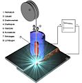
Schematic illustration of MSG soldering
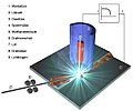
Schematic representation of TIG soldering

Schematic representation of plasma soldering


| Designation, material number: | SG-CuSi3 | SG-CuAl8 |
| Melting range in ° C: | 910 to 1025 | 1030 to 1040 |
| Yield strength R p 0.2 in N / mm²: | > 120 | 180 |
| Tensile strength R m in N / mm²: | 340 ... 460 | 380 ... 450 |
Sheet metal thicknesses of up to about 3 mm are soldered. The coating thickness should not significantly exceed 15 μm. The solder wires are 0.8 to 1.2 mm in diameter. Pure argon or argon with admixtures is used as the protective gas . Fillet, flanged and I-seams (see welding ) are common. Soldering on deformed contours under tensile stress should be avoided because of the risk of solder cracks.
In order to ensure occupational health and safety, the soldering fume must be extracted. There are protective gas burners with integrated suction. The accident prevention regulation BGR 220 and BGR 500 Chapter 2.26 (formerly BGV D1) apply.
Soldering in vehicle construction
MIG brazing has the advantage over welding in body and vehicle construction that changes in the structure of the base material and large-scale damage to the zinc coating are avoided because the component temperature essentially remains well below 1000 ° C. Corrosion protection and fracture behavior are not adversely affected. Another reason are quality problems when welding galvanized sheets due to the evaporation of the zinc (missing connection, formation of cavities).
Some vehicle manufacturers make MIG soldering mandatory for certain seams.
Also the resistance brazing is common in the body shop. In this case, the soldering point with the solder (e.g. a copper-silicon alloy) is heated with a high current through the body metal and only the solder melts.
With laser soldering , the solder is melted in the joint with a laser beam. Laser soldering is also used in body construction.
Soldering dangers

The soldering fumes produced during soft soldering in the electrical and electronics industry contain harmful substances. Due to the presence of flux, which contains colophony , ammonium chloride and organic acids , there is a health hazard that should not be underestimated. Respiratory organs and eyes are irritated and damaged. When inhaled, vapors can lead to headaches, symptoms of fatigue, conjunctival irritation and much more. Soldering fume extraction is therefore generally useful and prescribed at the workplace in accordance with DGUV Information 213-725 (previously BGI / GUV -I 790-025) of the German Statutory Accident Insurance, even for occasional soldering work. In industry, specially made extraction systems are often used for this purpose . Due to the composition of very different pollutants such as fine dust and solvent vapors, extraction systems for soldering fumes are often equipped with several filter stages. HEPA filters ensure the separation of particles, while activated carbon filters are designed to capture gaseous pollutants and unpleasant odors. When soldering work that is carried out above the head, the risk of tin dripping off is particularly high. In general, a soldering iron should never be held directly above the head.
literature
- Reinard J. Klein Wassink: Soft soldering in electronics . 2nd Edition. Eugen G. Leuze, Saulgau 1991, ISBN 3-87480-066-0 .
- Wolfgang Scheel (Hrsg.): Assembly technology of electronics . Verlag Technik et al., Berlin et al. 1997, ISBN 3-341-01100-5 .
- Brian Jepson, Tyler Moskowite, Gregory Hayes: Learn to Solder. Tools and Techniques for Assembling Electronics. 1st, new edition. O'Reilly & Associates, Sebastopol CA 2012, ISBN 978-1-4493-3724-7 .
Web links
- Environmentally friendly handicrafts - Telepolis has to be soldered without lead since July 2006
- The electronics compendium, soldering
supporting documents
- ↑ Since then, the use (storage, mixing, use for production, etc.) and placing on the market of lead - solid or as powder - has been banned with few exceptions if it is intended for sale to the general public and the lead concentration therein is 0.3% or is more, Art. 67 Paragraph 1 of Regulation (EC) No. 1907/2006 i. V. m. with Annex XVII No. 30 and Annex VI Part 3 to Regulation (EC) No. 1272/2008 (the so-called CLP Regulation ). The ban was implemented through the inclusion of lead in the list of substances hazardous to reproduction (here category 1A) by Commission Regulation (EU) 2017/1510 of 30 August 2017 . A violation of this prohibition is therefore in Germany according to § 5 No. 20 Chemical Sanctions Ordinance i. V. m. Section 27 of the Chemicals Act a criminal offense (as of June 2020)
- ↑ in Germany according to TRGS 505 ; there activity no. 5 of the lists no. 3.3 and Appendix 2
- ↑ rupert-trager.de: Lead-free solders (PDF; 408 kB).
- ↑ https://www.ipc.org/4.0_Knowledge/4.1_Standards/Free/j-std-006b-amendments1-2.pdf IPC J-STD-006B Amendment s1 & 2, September 2009: Requirements for Electronic Grade Solder Alloys and Fluxed and Non-Fluxed Solid Solders for Electronic Soldering Applications , page 6
- ↑ Soft soldering: The clean soldering seam (PDF; 425 kB) In: suissetec-INFO, Leaflet No. 2b . October 2006. Archived from the original on March 12, 2013. Retrieved March 20, 2013.
- ↑ https://www.wuerth.de/web/media/downloads/pdf/meinwuerth_1/downloadcenter/broschueren/loet_schweisstechnik.pdf Basic knowledge of welding processes in soldering and welding technology 2, company brochure of Adolf Würth GmbH & Co. KG, accessed on 11 AUG 2017.
- ↑ German statutory accident insurance e. V. (DGUV): Manual piston soldering with lead-free solder alloys in the electrical and electronics industry - recommendations for risk assessment by the accident insurance carriers (EGU) according to the Ordinance on Hazardous Substances. Process and substance-specific criterion (VSK) according to TRGS 420. Retrieved on June 28, 2019 .