
Resistance (component)

A resistor is a two-pole passive electrical component . It realizes an ohmic resistance in electrical and electronic circuits. For example, resistors are used to:
- limit the electric current
- to divide the electric current in a circuit
- to convert the electric current into a voltage in order to (indirectly) measure it
- to divide the electrical voltage in a circuit
- convert electrical energy into thermal energy
Main applications
- Setting or limiting an electrical current at a given electrical voltage ( series resistor )
- Setting a specific electrical voltage for a given electrical current (working resistance , shunt resistance )
- Dividing an electrical voltage in a certain ratio ( voltage divider ). For this purpose, at least two or more resistors are connected in series ( series connection ).
- Dividing an electric current in a certain ratio ( current divider ). For this purpose, at least two or more resistors are connected in parallel ( parallel connection ).
- Generation of a defined level in the event that a high-impedance connection of an integrated logic circuit is not wired or is connected to the rest of the circuit via an electrical open circuit ( pull-up / pull-down resistance)
- Generation of a defined level for setting operating points of active components, e.g. B. with transistor or operational amplifiers
- Conversion of electrical energy into thermal energy such as in light bulbs , soldering irons , equivalent loads , fan heaters or resistance brakes
- Establishing defined input and output impedances ( impedance matching )
Resistors can be designed in such a way that they serve as a fuse in the event of an overload . They must not catch fire. These include specially designed film resistors, but also PTC fuses .
General
A linear resistor (this includes all resistors whose resistance value, unlike non-linear resistors , does not depend on any other parameter) sets an electrical current proportional to the applied electrical voltage and vice versa. It serves as a current-voltage converter or as a voltage-current converter and cannot merely limit the current like an electrical fuse .
Parameters
.jpg)
In addition to the resistance value, the following additional values are characteristic of a resistor:
- Tolerance of the resistance value (delivery tolerance )
- maximum power dissipation
- maximum surface or film temperature
- Temperature coefficient (TK value, given in the form TKxxx with xxx = ppm per Kelvin temperature change)
- Dielectric strength
- Long-term stability ( drift ) with maximum power loss or nominal power over the service life
- Processing stability (soldering drift, if the processing includes a soldering process)
- parasitic inductance (lower with low-inductance resistors)
- parasitic capacitance
- Current noise (current noise not only increases with the resistance value, but is also material and voltage dependent (µV / V))
- Impulse load capacity (short-term overload capacity), maximum crest factor for periodically changing loads from alternating current or periodic pulses
- Voltage dependence of the resistance value (important for high-resistance measuring resistors)
Classification
Electrical resistances as a component can be grouped according to various criteria, for example:
- power
- Resistance material
Another classification is that according to use (decreasing requirements for accuracy and long-term stability):
- Precision resistance (<0.1%, in analog circuits with operational amplifiers)
- Measuring resistor (<0.5%, see also shunt )
- Voltage divider , variable resistor (fixed or variable in the form of a potentiometer or trimming resistor)
- Working resistance , series resistance , general applications in electronic circuits (1–5%, bulk goods), terminating resistor (see dummy load )
- Pull-up / pull-down resistor, digital circuits (> 10%, often as resistor arrays )
Designs and materials


An important material parameter is the specific resistance .
The best-known resistor design is the cylindrical ceramic carrier with axial connection wires. These connecting wires are fed through holes in circuit boards , for example , and soldered to the conductor track connections arranged there. A ceramic carrier is coated with the resistance material, which receives its desired resistance value either through its composition, layer thickness or through notches (coiling). The maximum power loss is between 0.1 W and 5 W.
The axial design with a square cross-section (see photo, first from above) is usually chosen for wire resistors and is filled with quartz sand. These resistors are designed for higher power losses.
The meander shape is a special design. This form can be found in power and high-power resistors. The advantage of this structure is that you can accommodate a long conductor length in a small area. Manufacturing on bending or milling machines is also relatively easy. The meandering shape can be clearly seen, for example, in fan heaters and Manganin ceramic resistors.
As with all electrical engineering components, SMD versions of resistors are also produced. The widespread chip designs are small cuboids with, for example, 1 mm × 2 mm × 0.5 mm edge length, which have metallizations as contacts on the two smallest surfaces. These are connected directly to a circuit board by soldering (surface mounting).
The various materials of the resistance layers are selected according to the desired accuracy ( tolerance ) and temperature stability. Coal layers have a negative temperature coefficient and are very imprecise. Metal film resistors can be manufactured with the highest accuracy and, depending on the alloy, with very low temperature coefficients. Metals generally have a positive temperature coefficient . Metal film resistors are also manufactured as fuse resistors - these cause a safe interruption of the current flow in the event of overload.
Metal oxide film resistors are manufactured for very high resistance values and high voltages. These are particularly stable in relation to the migration processes that occur at high voltages .
Very small, highly resilient resistors (e.g. shunts and braking resistors for high energy absorption) are made of metal foil ( Manganin ). If these resistors are used for current measurement (shunts), they often have so-called Kelvin connections , i.e. two additional connections, in order to avoid the measurement error caused by the voltage drop at the contact.
Electrical resistors are available as electronic components in various designs, which differ, for example, in the type and shape of the resistance material:
-
Film resistances :
- Carbon film resistor
- Metal film resistor
- Metal oxide (also MOX) sheet resistor
- Cermet (also thick film ) resistor
- Photo resistor (LDR for short, light-dependent resistor, for example made of a cadmium sulfide layer)
- Foil resistors (planar) and massive metal resistors
- Braking resistor (high load capacity for a short time)
- Shunt resistance (sheet metal or foil, also in the form of several parallel rods, often with Kelvin contact )
-
Ground resistances
- Carbon mass resistance
- Ceramic ground resistance
- Thermistor - (NTC) and PTC - (PTC) resistors
- Varistor (VDR for short, voltage-dependent resistor)
- Wire resistance
- Potentiometer (changeable resistance)
Furthermore one knows
- designs suitable for high frequency such as the Möbius resistor . These designs are low-induction, uncoiled, there are also coaxial designs. Applications are, for example, terminating resistors .
- Designs suitable for high voltages (long length, mostly made of metal oxide).
- the use of resistance material for heating or defrosting .
In a monolithic integrated circuit (base material monocrystalline silicon) the choice of resistance materials is very limited. A specially wired transistor is often used as a replacement resistor for each required resistor, since “real” resistors require more space in the layout. If real resistors are required in the circuit, polymorphic silicon is usually used .
Fixed resistors
Properties of fixed resistors
Fixed resistors are ohmic resistances with a fixed, i.e. H. non-adjustable resistance values. They are determined by:
- Nominal resistance,
- Resilience,
- Delivery tolerance,
- Grade.
The nominal resistances are graded according to certain series of norms. Such a gradation is necessary for economic reasons. Fixed resistors cannot be made with any resistance value. If you need a specific resistance value that is not included in the standard series, you can use an adjustable resistor and set it to the desired value. Nowadays, fixed resistors are manufactured almost exclusively according to the internationally valid IEC series of standards .
Gradation of the resistance values

The nominal values of resistors are graded according to geometric sequences . Each decade has the same number n different values graded with the factor q = 10 (1 / n ) . The E series graded with n = 3 · 2 a ( a is an integer) are internationally valid . Depending on the tolerance, resistors can be manufactured with values from the E12 (10%), E24 (5%), E48 (2%) or E96 series (1%). The percentage numbers indicate minimum accuracies for the respective series.
For example, the values in the series E12 = {10, 12, 15, 18, 22, 27, 33, 39, 47, 56, 68, 82}. The values are chosen so that there are overlapping tolerance ranges. As a side effect, a minimal number of storage values is achieved.
To put it another way and more simply: The E series indicate how many resistances there are per decade (e.g. from 100 Ω to 1 kΩ). For example, E12 has twelve resistors, the distance between which is geometrically (almost) evenly distributed. In the past, only the E12 series was common, but nowadays there are more accurate and more stable resistors.
Due to the coordinated combination of E series and tolerance range, there is an associated nominal value for any resistance value, so that, in principle, any resistance values could be produced with a diversified manufacturing process, which could then be more precisely tolerated by selection. However, this is undesirable because the required numbers of pieces, even for neighboring values, are very different. Today it is possible to manufacture resistors with a high level of stability and to control the process parameters in such a way that resistors in the desired values of the E96 series or all other series with a usual tolerance of 1% are created without readjustment, all of which can be set off.
Sizes of wired resistors
In industry, wired resistors are rarely used for circuit board assembly. They are still very widespread in the non-professional sector, because processing is very simple and, unlike circuit board assembly with sometimes very small SMD components, requires little soldering experience.
The design 0207 with axial connections and a resistor body approx. 2.3 mm in diameter and 6 mm in length is the most common design of low-power wired resistors for outputs of up to 0.25 W (carbon film resistors) or 0.5 W (metal film resistors). Less common are leaded miniature resistors of the type 0204 with a resistor body of approx.1.5 mm diameter and 3.2 mm length for maximum powers between 0.1 W and 0.25 W. These correspond in size to the SMD type MINI-MELF ( 0204), but have axial connection wires.
Types and sizes of SMD resistors

SMD resistors are miniature resistors for direct soldering on the circuit board surface. Due to their small dimensions, they enable the construction of compact devices.
In addition, this type of construction has significant advantages over wired components in HF technology , since the inductances resulting from resistance windings and connecting wires are eliminated or greatly reduced.
SMD resistors are available in round ( MELF ) and cuboid designs. SMD-MELF resistors (MICRO-MELF 0102, MINI-MELF 0204, MELF 0207) are used in professional applications in industrial and automotive electronics, where high power losses, ambient temperatures, pulse loads and a small change in resistance over time (drift) are necessary . They are available as thin-film or metal-film, metal glaze and carbon film resistors. Their sizes are pad-compatible with the chip designs listed below:
- MICRO-MELF 0102 is compatible with chip design 0805
- MINI-MELF 0204 is compatible with the chip design 1206
- MELF 0207 is compatible with chip design 2512
The majority of the SMD resistors used are cuboid (chip resistors); they are offered as thin and thick film resistors. The following remarks refer to this design.
SMD components are available in various sizes, among others
- 2512, 2010, 1218, 1210, 1206, 0805, 0603, 0402, 0201, 01005
With the larger designs (from 0402) the first two digits indicate the length and the last two the width of the component in units of about 1/100 inch (= 0.254 mm ). or 0.250 mm. For example, a 0805 resistor is 2 mm long and 1.25 mm wide. This assignment is no longer correct for types 0201 and smaller.
Details: chip design , surface mounted device
In many series, the height is slightly greater than 0.635 mm (1/40 inch = 25 mil , this is a common thickness of the aluminum oxide ceramic substrates used as the starting material), but generally not greater than the width of the component (due to otherwise difficult assembly, Danger of tipping).
Different maximum power losses and maximum voltages are permitted for the various designs:
| Design | Max. Power loss in watts | Max. Voltage in volts |
|---|---|---|
| 2512 | 1 | 500 |
| 2010 | 0.75 | 400 |
| 1218 | 1 | 200 |
| 1210 | 0.5 | 200 |
| 1206 | 0.25 | 200 |
| 0805 | 0.125 | 150 |
| 0603 | 0.1 | 75 |
| 0402 | 0.063 | 50 |
| 0201 | 0.05 | 30th |
| 01005 | 0.03 | 15th |
| MICRO-MELF (0102) | 0.3 | 150 |
| MINI-MELF (0204) | 0.4 | 200 |
| MELF (0207) | 1 | 300 |
Information on resistances
Rounded resistors for electronic circuits are often not or cannot be printed with numbers. Color coding is used to mark their values. With today's, even smaller but flat SMD resistors, the characteristic values are applied by printing or laser engraving.
Alphanumeric labeling
The letter "R" can be used as a decimal separator for compact alphanumeric labeling of resistance values:
- 10R = 10 Ω
- 1R5 = 1.5 Ω
- R005 = 0.005 Ω = 5 mΩ
In the same way, the SI prefixes can also be used as decimal separators. The value of the prefix represents an additional multiplier:
- 10k = 10 kΩ
- 1M5 = 1.5 MΩ
- 0k5 = 0.5 kΩ = 500 Ω
This form of representation is mainly used in circuit diagrams .
Information on SMD resistors
The labeling depends on the E series and the size of the components.
The larger the E series, the smaller the tolerances of the components: E3 = over 20%, E6 = 20%, E12 = 10%, E24 = 5%, E48 = 2%, E96 = 1%, E192 = 0, 5%
For reasons of space, SMD resistors of type 0402 and smaller are generally not printed.
Resistors of type 0603 and larger are usually marked as follows (there are also series from manufacturers where the resistors are not marked at all; this applies in particular to 0603):
SMD resistors of tolerance class> = 5% are generally marked with three digits. The first two digits indicate the resistance value, the third the power of ten, which is multiplied by the value of the first two digits, in simplified terms: the number of trailed zeros.
- 472 = 47 × 10 2 = 47 × 100 = 4700 Ω = 4.7 kΩ
- 104 = 10 × 10 4 = 10 × 10000 = 100,000 Ω = 100 kΩ
- 101 = 10 × 10 1 = 10 × 10 = 100 Ω
- For values below 10 Ω, 'R' replaces the decimal point: 1R0 = 1.0 Ω
SMD resistors of tolerance class <5% are printed with four digits if there is enough space for them (generally from design 0805 or 1206). The first three digits indicate the resistance value, the fourth the power of ten, which is multiplied by the value of the first three digits, in simple terms: the number of zeros attached.
- 1002 = 100 × 10 2 = 100 × 100 = 10,000 = 10 kΩ
- 1003 = 100 × 10 3 = 100 × 1000 = 100,000 = 100 kΩ
- For values below 100 Ω, an “R” replaces the decimal point: 10R0 = 10.0 Ω
Resistors of type 0603 and 1% tolerance are either not marked or marked with three characters. With a resistance value from the E24 series or coarser, the components are marked with a 5% tolerance (see above), but the middle number is also underlined. For resistors from a finer E series (e.g. E96), two digits are not sufficient for the resistance value. For this purpose, the resistance value is coded by a (continuously counted) two-digit number, the exponent by a letter, in order to be able to distinguish this code reliably from the other type of identification.
Further articles on SMD resistors: Metal Electrode Faces , chip design
Color coding on resistors


The resistor color coding or color coding for resistance is a color marking for the electrical values of resistors. As electronic components , these are often very small and also cylindrical, making it difficult to print legible numbers on them. Instead, surrounding colored rings indicate the resistance value and the tolerance class.
There are color codes with three, four, five or six rings. With three or four rings, the first two rings give a two-digit value from 10 Ω to 99 Ω (see table below), and the third ring gives a multiplier ( power of ten from 10 −2 to 10 9 ) with which the value is added multiply is. This means that 1080 different resistance values can be expressed. The fourth ring, if present, indicates the tolerance class. If it is missing, the tolerance is ± 20%. With five or six rings, the first three rings indicate the value (100 to 999 Ω), the fourth ring is the multiplier and the fifth ring is the tolerance class. If there is a sixth ring, it indicates the temperature coefficient (stability).
The reading direction is marked in two different ways: either the first ring is less distant from the edge of the resistor body than the last ring, or the last ring is spatially separated. Check: The other reading direction does not give a value for the associated E series or cannot be deciphered at all (e.g. the last ring is silver or gold, which is not permitted for the first ring).
The color coding is specified in DIN IEC 62, or for resistors with specification of the temperature coefficient according to DIN 41429 as follows:
| colour | Resistance value in Ω | tolerance | |||
|---|---|---|---|---|---|
| 1st ring (tens) |
2nd ring (one) |
3rd ring (multiplier) |
4th ring | ||
| "no" | × | - | - | - | ± 20% |
| silver | - | - | 10 −2 = 0.01 | ± 10% | |
| gold | - | - | 10 −1 = 0.1 | ± 5% | |
| black | - | 0 | 10 0 = 1 | - | |
| brown | 1 | 1 | 10 1 = 10 | ± 1% | |
| red | 2 | 2 | 10 2 = 100 | ± 2% | |
| orange | 3 | 3 | 10 3 = 1,000 | - | |
| yellow | 4th | 4th | 10 4 = 10,000 | - | |
| green | 5 | 5 | 10 5 = 100,000 | ± 0.5% | |
| blue | 6th | 6th | 10 6 = 1,000,000 | ± 0.25% | |
| violet | 7th | 7th | 10 7 = 10,000,000 | ± 0.1% | |
| Gray | 8th | 8th | 10 8 = 100,000,000 | ± 0.05% | |
| White | 9 | 9 | 10 9 = 1,000,000,000 | - | |
High accuracy resistors usually have five or six rings. If there are five rings, the first three indicate the values, ring four the multiplier and ring five the tolerance. A sixth ring indicates the temperature coefficient .
| colour | 1st ring (hundreds) |
2nd ring (tens) |
3rd ring (one) |
4th ring (multiplier) |
5th ring (tolerance) |
6th ring (temperature coefficient) |
|---|---|---|---|---|---|---|
| silver | 10 −2 | |||||
| gold | 10 −1 | |||||
| black | 0 | 0 | 10 0 | 200 10 −6 K −1 | ||
| brown | 1 | 1 | 1 | 10 1 | ± 1% | 100 10 −6 K −1 |
| red | 2 | 2 | 2 | 10 2 | ± 2% | 50 10 −6 K −1 |
| orange | 3 | 3 | 3 | 10 3 | 15 10 −6 K −1 | |
| yellow | 4th | 4th | 4th | 10 4 | 25 10 −6 K −1 | |
| green | 5 | 5 | 5 | 10 5 | ± 0.5% | |
| blue | 6th | 6th | 6th | 10 6 | ± 0.25% | 10 10 −6 K −1 |
| violet | 7th | 7th | 7th | ± 0.1% | 5 10 −6 K −1 | |
| Gray | 8th | 8th | 8th | ± 0.05% | ||
| White | 9 | 9 | 9 |
- Examples
- The yellow-violet-red-brown colored rings mean 47 · 10 2 Ω = 4.7 kΩ and a tolerance of ± 1%. This results in a possible tolerance range of 4.653 kΩ to 4.747 kΩ for the resistance.
- A resistor with the five rings green – brown – brown – orange – blue has a nominal value of 511 · 10 3 Ω = 511 kΩ and has a tolerance of ± 0.25%.
EIA-96 coding on resistors
With the EIA -96 coding, two digits are given as the code for the value and one letter as the multiplier.
- value
| code | value | code | value | code | value | code | value | code | value | code | value | code | value | code | value | |||||||
|---|---|---|---|---|---|---|---|---|---|---|---|---|---|---|---|---|---|---|---|---|---|---|
| 01 | 100 | 13 | 133 | 25th | 178 | 37 | 237 | 49 | 316 | 61 | 422 | 73 | 562 | 85 | 750 | |||||||
| 02 | 102 | 14th | 137 | 26th | 182 | 38 | 243 | 50 | 324 | 62 | 432 | 74 | 576 | 86 | 768 | |||||||
| 03 | 105 | 15th | 140 | 27 | 187 | 39 | 249 | 51 | 332 | 63 | 442 | 75 | 590 | 87 | 787 | |||||||
| 04 | 107 | 16 | 143 | 28 | 191 | 40 | 255 | 52 | 340 | 64 | 453 | 76 | 604 | 88 | 806 | |||||||
| 05 | 110 | 17th | 147 | 29 | 196 | 41 | 261 | 53 | 348 | 65 | 464 | 77 | 619 | 89 | 825 | |||||||
| 06 | 113 | 18th | 150 | 30th | 200 | 42 | 267 | 54 | 357 | 66 | 475 | 78 | 634 | 90 | 845 | |||||||
| 07 | 115 | 19th | 154 | 31 | 205 | 43 | 274 | 55 | 365 | 67 | 487 | 79 | 649 | 91 | 866 | |||||||
| 08 | 118 | 20th | 158 | 32 | 210 | 44 | 280 | 56 | 374 | 68 | 499 | 80 | 665 | 92 | 887 | |||||||
| 09 | 121 | 21st | 162 | 33 | 215 | 45 | 287 | 57 | 383 | 69 | 511 | 81 | 681 | 93 | 909 | |||||||
| 10 | 124 | 22nd | 165 | 34 | 221 | 46 | 294 | 58 | 392 | 70 | 523 | 82 | 698 | 94 | 931 | |||||||
| 11 | 127 | 23 | 169 | 35 | 226 | 47 | 301 | 59 | 402 | 71 | 536 | 83 | 715 | 95 | 953 | |||||||
| 12 | 130 | 24 | 174 | 36 | 232 | 48 | 309 | 60 | 412 | 72 | 549 | 84 | 732 | 96 | 976 |
The EIA-96 table values can also be calculated using the following formula:

- multiplier
- Y = 10 −2 , X = 10 −1 , A = 10 0 , B = 10 1 , C = 10 2 , D = 10 3 , E = 10 4 , F = 10 5
- Examples
- 01Y = 1 ohm
- 02X = 10.2 ohms
- 03A = 105 ohms
- 04B = 1.07 kOhm
Parameter-dependent resistances
Parameter-dependent resistances are also referred to as non-linear resistances . An essential feature is that the resistance value depends on one or more other physical parameters such as the voltage applied to the resistor, the temperature, pressure, the incidence of light and the like. It is essential that in non-linear resistors, the relationship between voltage and the current through the resistor not by ohmic relationship with a constant resistance value R can be described.
Temperature-dependent resistances
Thermistors are resistors with a deliberately pronounced temperature dependence . One differentiates:
- PTC resistors (PTC thermistors , positive temperature coefficient): the resistance value increases with increasing temperature, used as a temperature sensor, as a self-resetting fuse, as a self-regulating heating element and to control the demagnetization of picture tubes.
- NTC resistors ( thermistor , negative temperature coefficient): the resistance value decreases with increasing temperature, among other uses as a temperature sensor and for inrush current limitation.
The iron-hydrogen resistance also has a PTC behavior. It was previously used as a current stabilizer in the heating circuits of tube devices and works due to the self-heating of an iron wire in hydrogen.
Photoresistors

A photo resistor, called LDR (Light Dependent Resistor) for short, changes its resistance when exposed to light. If light hits the photosensitive surface of the photoresistor, the resistance is reduced due to the internal photoelectric effect .
Voltage-dependent resistances
They are called varistors (an artificial word made up of “variable” and “resistor”) and consist of metal oxides (mostly doped zinc oxide). They reduce their resistance value with increasing voltage, usually drastically from a characteristic threshold voltage similar to a Zener diode (but for both polarities). They are used to limit overvoltage pulses (threshold voltages from 5 volts to several kilovolts), but not for voltage stabilization.
Abbreviations such as MOV ( metal oxide varistor ) or VDR (of English. Voltage dependent resistor ) are derived from material and behavior.
Coherers contain charcoal and reduce their resistance value through high-frequency currents.
Resistance dependent on pressure and strain
- Strain gauges are foil resistors that are glued on. They change their resistance value depending on their elongation or tensile stress .
- Resistors made from stacks of graphite disks reduce their resistance to pressure. They can withstand high power losses and were previously used to control motors (sewing machines) and operated with a pedal.
- The carbon microphones , which are not referred to as resistance, change their resistance value through the changing pressure of a sound- receiving metal membrane on a charcoal filling.
Adjustable resistances
- An electrical resistance component whose resistance value can be changed mechanically during normal operation, such as by turning or moving an actuator, is called a potentiometer. It has three connections, those of the simple component resistance and a third wiper connection for tapping the set resistance value. Potentiometers are suitable for frequent adjustments. Main applications are level adjustment or acquisition of an angular or lateral position.
- Trimming potentiometers (low power) and variable resistors (high power) are only suitable for occasional adjustments, for example as part of a one-off adjustment process during production.
- Historically, variable power resistors were referred to as rheostat - in the English-speaking world, the term rheostat for variable wire resistance is still common today.

A resistance that can be adjusted by turning, the potentiometer
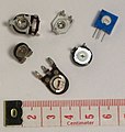
Trim resistors

Variable power resistance, known in English as a rheostat
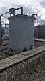
Water resistance in a substation


In special applications, water resistors are also used for starting slip-ring motors in the form of liquid starters or as a comparatively inexpensive power resistor, for example for neutral point treatment in substations. Electrodes are immersed in a closed water container. With some designs, the resistance value can be varied by the immersion depth of the electrodes.
Web links
Individual evidence
- ↑ Klaus Beuth: Components Electronics 2 . Vogel Business Media, Würzburg 2010, ISBN 978-3-8343-3170-0 , p. 25 .
- ↑ color code resistance. the Resistor Guide, accessed December 12, 2012 .
- ↑ Data sheet Yageo Chip Resistors. (PDF) www.yageo.com, accessed on September 22, 2014 (English).