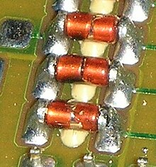
Metal Electrode Faces
Metal Electrode Leadless Faces (MELF) is a cylindrical design of SMD components with two connections. With her, the end faces are designed as contacts. Connection lugs or wires are missing (leadless). Usually these are diodes for which this design is selected.
The design is also used for thermistors ( NTC , PTC ) and resistors .
Special features of MELF resistors
Although they are much larger and more expensive than similar chip SMD components , resistors in the MELF package are also used in electronics production. This is mainly due to the fact that components with better parameters (compared to other types) with regard to pulse current load capacity, temperature stability, drift (long-term stability) and dielectric strength as well as with a precisely specified behavior in the event of a fault are usually manufactured in the MELF housing. While an unspecified resistor will unpredictably become either high or low in the event of a fault, an appropriately designed resistor can only become high ohm due to its structure.
Disadvantages of MELF
The disadvantage of the MELF housing is that the components tend to roll away when they are assembled. That is why MELFs are often glued before they are soldered.
Designs and sizes
The types of construction for SMD-MELF resistors are defined in accordance with EN 140401-803 or DIN EN 140401-803, whereby the four-digit code defines the DIN specifications for diameter and component length in mm. The information is subject to the tolerances of the respective manufacturer. The following information refers to the SMD-MELF resistors from the manufacturer Vishay Beyschlag.
Melf      (MMB) 0207  L=5,8 mm, ⌀=2,2 mm      0,4  … 1 W     350 V
MiniMelf  (MMA) 0204  L=3,6 mm, ⌀=1,4 mm      0,25 … 0,45 W  200 V
MicroMelf (MMU) 0102  L=2,2 mm, ⌀=1,1 mm      0,2  … 0,3 W   150 V
- The specified range of power loss corresponds to the range spanned by the two operating modes Standard and Power specified by the manufacturer .
- Micro-MELF 0102 is compatible with the footprint of the chip design 0805 (approx. 2 mm × 1.25 mm).
- Mini-MELF 0204 is compatible with the footprint of the chip design 1206 (approx.3.2 mm × 1.6 mm).
- MELF 0207 is compatible with the footprint of the chip design 2512 (approx. 6.35 mm × 3.2 mm).
Similar designs
Individual evidence
- ↑ MMU 0102, MMA 0204, MMB 0207 - data sheet . Website manufacturer.
