
Fuse
A fuse is an overcurrent protection device that breaks the circuit by melting a fuse element if the current strength exceeds a certain value for a sufficient period of time.
Until now, the fuse in the electrotechnical literature was simply referred to as a fuse and this term was rejected for other protective devices such as miniature circuit breakers , self-resetting fuses and electronic fuses . The term is defined in DIN EN 60269-1 (VDE 0636-1).

Layout and function
Fuses consist of an insulating body that accommodates two electrical contacts connected by a fusible link. The fuse element is heated by the current flowing through it and melts when the rated current of the fuse is clearly exceeded for a certain time. This protective function is called "tripping the fuse". Blown fuses are unusable and must be replaced.
The fusible conductor is usually made of electrolytic copper (E-CU) or fine silver (Ag 1000/1000) and is surrounded by air or quartz sand .
The sand serves as an arc extinguishing agent. When a circuit is switched off, an arc is created , the intensity of which u. a. depends on the level of the current to be switched off . In the event of a short circuit, this current can be several orders of magnitude higher than the rated current of the fuse.
The fusible conductor passes through the three physical states (solid, liquid, gaseous) during response. In the gaseous state of the fusible conductor, a plasma is created and the current flows through it - an arc is formed that heats the quartz sand strongly. The melting quartz sand cools the arc so intensely that it is effectively prevented from being ignited again when the voltage returns after the zero crossing (with alternating current). In the area of influence of the arc, a non-conductive sintered body is created made of fusible metal, solder and quartz, which is also known as a "melt bead" because of its appearance. The arc extinguishes and the line to be protected is thus separated from the supplying current or voltage source. This is the most important function of the backup. A secondary function is the ability to de-energize the circuit by removing the fuse. This is only possible with permanent installations, since with single-pole fused devices ( protection class II ) the fuse can happen to be in the neutral conductor.
The correct function of the arc extinguishing system is essentially dependent on the grain size, the purity and the packing density of the quartz sand used. The extinguishing agent must be absolutely free of organic compounds. The feldspar components that often accompany the quartz sand must be completely removed, as feldspar promotes the glass flow of the sand. Glass flow inside a fuse link must not occur because glass is electrically conductive when it is glowing.

Fuse links are mostly used in the appropriate socket . Sockets are sometimes dispensed with on circuit boards and the fuses are attached by soldering . In individual cases, a wire or conductor track section serves as a backup. Also resistors can be specified as a backup (so-called. Fuse resistance ). In addition to their resistance value, they also have a defined burn-off behavior in the event of overload.
Switching capacity
So that a fuse can safely trip in the event of a short circuit, it is important that its breaking capacity (breaking capacity) is not exceeded. The switching capacity is the maximum expected "prospective" (unaffected) short-circuit current that the fuse can safely switch off without stopping an arc or destroying the fuse itself (e.g. bursting the ceramic body).
The specification of the switching capacity only makes sense together with the operating voltage and type of current:
- The switching capacity decreases with increasing operating voltage. Sometimes different values are given for different voltages.
- The switching capacity decreases with decreasing alternating current frequency. Unless otherwise specified, the rated frequency is 45 Hz to 62 Hz.
- The switching capacity for direct current is significantly lower than for alternating current. Fuses that are intended for direct current can also be used for alternating current without hesitation, but not vice versa.
The breaking capacity of the various fuse types is given in the relevant sections.
Device protection fuses (fine fuses)
Fuses, shortly GS fuses or G-fuses called consist of a small glass or ceramic tube with metal caps at both ends, between which the fuse wire is. This fuse wire is exposed or embedded in quartz sand. They are also referred to as device fuses , microfuses and, if applicable, as glass tube fuses .
G fuses are manufactured for nominal currents of 0.032… 32 A with breaking capacities of around 32 A to 150 kA.
They are available in different lengths and diameters. The most common in Europe is 5 × 20 mm and in the US ¼ × 1¼ in. (6.3 × 32 mm).
Areas of application: device protection (often found in commercial power supplies), fuse terminals in control cabinets and (less often) vehicle electrics.
Labelling
The nominal current, the maximum voltage and the (tripping) characteristic are stamped on the metal caps. Color coding or an imprint of the values on the glass tube are less common.
| Embossing | Characteristic |
|---|---|
| FF | super nimble |
| F. | nimble |
| M. | medium inertia |
| T | sluggish |
| TT | super yield |
| Breaking capacity typical values at 250 V AC |
typical design | ||
|---|---|---|---|
| L. | low | 10 × I n (min. 35 A) | Glass tube |
| E. | elevated | min. 100 A | Glass tube, reinforced or filled |
| H | high | min. 1500 A | Ceramic tube, filled with sand |
Parameters for device protection fuses are nominal current, nominal voltage, tripping characteristics, breaking capacity and melting integral . The characteristic is determined by characteristic curves and differentiates between fast, medium time lag and time lag fuses. Switch off at ten times the nominal current:
- fast-acting fuses in less than 20 ms
- medium-time fuses between 50 and 90 ms
- slow fuses between 100 and 300 ms.
Microfuses with high breaking capacity are filled with sand or have a ceramic body.
The definition of the nominal current and the response behavior of American fuses (6.3 × 32 mm) differs from European types, so they are usually not interchangeable with the same current values.
Release behavior
The tripping time depends on the characteristic as well as the current as a factor of the nominal current. The fuse rating is by no means a hard limit that will trigger a fuse if it is minimally exceeded. Inert glass fuses (according to EN 60127-2 sheet 3) must hold 1.5 times the nominal current for at least one hour. I.e. the fuse must not trigger. At 2.1 times the rated current, it must trigger after 2 minutes at the latest, at 4 times after 3 seconds and at 10 times after 0.3 seconds at the latest.
The required or undesired triggering of a fuse by a brief high current surge z. B. when switching on a transformer is related to the melting integral of the fuse. The melting integral is a value of current and time, I²t with the unit A²s. In the example with the inrush current on the transformer, 10 to 20 times the rated current of the transformer must be expected for a few milliseconds. If this value is greater than the melting integral of the required fuse, an inrush current limitation is also required.
Fine fuses with wire connections
Device fuses are also made with wire connections (axial or radial) for direct soldering into circuit boards.
British fuses according to BS 1362
In Great Britain and some other countries, miniature fuses ( fast-acting ) according to BS 1362 are built into the power plug . They are necessary because conventional sockets there are usually fused with 25, 30 or 32 A. Characteristic values:
- Dimensions: ¼ inch × 1 inch (6.3 × 25.4 mm)
- available values: 1, 2, 3, 5, 7, 10 and 13 A; Standard values: 13 A (brown) and 3 A (red)
- high switching capacity (6000 A at 240 V AC), therefore made of ceramic tube with sand filling
Types of microfuses
The following pictures illustrate the different types of microfuses
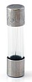
Microfuse 5 × 20 mm

Microfuse with glass housing (with and without sand filling) and with ceramic housing (also with sand filling)
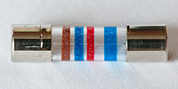
Microfuse 5 × 20 mm with color coding similar to that of electr. Resistances . The colored rings mean br (1) -bl (6) -rt (2 zeros) -bl (trigger characteristic) and stands for 1600 mA, medium slow

Size comparison (from left to right: 5 × 20 mm; 6 × 30 mm; 6.3 × 32 mm (¼ × 1¼ inches); 6.3 × 40 mm; 10 × 34.9 mm)

Device fuse 5 × 20 mm, for soldering into printed circuit boards (defective)


Extra-low voltage fuses, automotive fuses

Fuses for low voltages of typically 12 V, 24 V or 48 V (up to a maximum of 50 V AC or 120 V DC).
The fuses installed in motor vehicles are standardized in Germany according to DIN 72581. Plug-in fuses that can be maintained by the user are common.
Torpedo fuses

This design according to DIN 72581-1 was mainly used in European vehicles until the 1980s.
- Breaking capacity: 500 A at 36 V DC
- Permissible voltage drop across the safety strip according to DIN: 0.1 V
- Design: cylindrical insulating body, diameter: 6 mm, length: 25 mm.
The securing strip with conical contact surfaces on the end face is inserted in a groove. - Other names: ATS fuse, BOSCH fuse
| 5 A | 8 A | 10 A | 16 A | 25 A | 40 A |
|---|---|---|---|---|---|
| yellow | White | green | red | blue | Gray |
For the insulating support body, up to 5 A of thermoplastic material is permissible, above that the material must be heat-resistant. Ceramic is ideal for this . Colored glass and heat-resistant plastics are also common. A disadvantage is the small, ring-shaped contact surface, which can cause high contact resistances if the pressure force of the perforated retaining spring is insufficient. These lead to excessive heating of the contact point, which favors further oxidation of the contact point, which is already damaged.
Plug fuses
Blade fuses

The flat plug fuse design developed in 1976 is standardized in accordance with ISO 8820-3 and is only used for extra-low voltages, mainly in motor vehicles .
- Breaking capacity: 1000 A at 32 V DC (or 58 V DC)
In contrast to the ATS fuses, this design is certified by Underwriters Laboratories (UL).
A common brand name is ATO -Fuse, ( A utomotive T echnology O rganization); this is a registered trademark of Littelfuse Incorporated , USA.
Common designs are the standard flat fuse and the mini flat fuse.
| Type | Alternative names | Dimensions L × W × H | Connector width | Usual nominal currents |
|---|---|---|---|---|
| Low-profile mini fuse | 10.9 x 3.81 x 8.73 mm | 2; 5; 7.5; 10; 15; 20; 25; 30th | ||
| Mini fuse (mini fuse) | FK1; Mini; | 10.9 x 3.6 x 16.3 mm | 2; 3; 4; 5; 7.5; 10; 15; 20; 25; 30th | |
| Standard plug-in fuse (regular ATO fuse) | FK2; Midi; FKS; TF | 19.1 x 5.1 x 18.5 mm | 6.3 mm | 1; 2; 3; 4; 5; 7.5; 10; 15; 20; 25; 30; 35; 40 |
| Maxi plug-in fuse | FK3; Maxi | 29.2 x 8.5 x 34.3 mm | 20; 25; 30; 35; 40; 50; 60; 70; 80; 100; 120 |
The rated amperage of standard and mini blade fuses is identified by the color of their plastic body.
| 1 A | 2 A | 3 A | 4 A | 5 A | 7.5 A | 10 A | 15 A | 20 A | 25 A |
|---|---|---|---|---|---|---|---|---|---|
| black | Gray | violet | pink | light brown | brown | red | blue | yellow | frosted |
| 30 A | 40 A | 50 A | 60 A | 70 A | 80 A | 100 A | |||
| blue green | orange | red | blue | light brown | clear | violet | |||
Block fuses
.jpg)
So-called block fuses or JASO fuses are mainly used in Japanese vehicles and are standardized according to JASO D612-4: 2001 . Fuses with socket contacts and sockets are common; the force required for plugging is specified.
The brand name JCASE is also a registered trademark of Littelfuse Incorporation.
The usual sizes are JCASE and Low Profile JCASE.
Strip fuses
.JPG)
For currents over 40 A, there are strip fuses or blade fuses according to the withdrawn DIN 43560 or DIN 72581. Other names or designs are ANL fuse or ANL strip fuse or BF1 fuse. Because of the high electrical currents, the contact load with the contact resistance of the common plug-in contacts, which cannot be reduced at will, would be too great, so such fuses are screwed on and do not count among the fuses that can be repaired by laymen . They consist of a punched-out strip of locking plate. In addition to the open design, the closed design B / BN is also common. Some strip fuses have a ceramic housing and viewing window, others have a plastic insulating body. The housing serves as fire protection in the event that an accidental arc can develop during the burnout at over 24 V.
Such fuses are often located in vehicles in the immediate vicinity of the starter battery in a fuse box ; Installation on the battery itself is also common.
Also in electric vehicles, e.g. B. in forklifts , this type of fuse is common.
Strip fuses are reliably exchanged only with a tool and thus are legally doing with the lay unserviceable components.
In motor vehicles with internal combustion engines, fuses are mostly used for economic reasons. For safety reasons, electric window lifters also have electronic fuses. See there under anti-trap protection .
Low voltage fuses
Low voltage fuses according to IEC 60269 (formerly IEC 269, corresponds to EN 60269 and VDE 0636) are used in distribution networks , in industry and by end users, e.g. B. in the fuse box . The typical nominal voltage is 230/400 V AC. For industrial plants there are versions up to 1000 V DC or AC voltage.
There are different designs (e.g. screw fuses , NH fuses , cylinder fuses ), which in turn are manufactured in different operating classes (trigger characteristics).
Tripping characteristic or operating class

Like other fuse elements , fuses are characterized by their tripping characteristics. Together with the rated current and the switching capacity, it is an important parameter.
The tripping characteristic describes in a time-current diagram the tolerance field of the tripping time for certain relative overcurrents related to the nominal current. The tolerances with the same characteristics are relatively large. With a 1.5-fold overload, the tripping time is about one hour; at 15 times the nominal current (short circuit), for example, less than 50 ms. It is characteristic of all time-current diagrams of fuse elements that the tolerance range is greater for low overcurrent than for relatively high overcurrent. If tight shutdown tolerances are required (e.g. to protect a small transformer against overload), a fuse is often unsuitable. Alternatively, temperature fuses or bimetal overcurrent switches are used.
The characteristics of microfuses are described in the corresponding section above.
Time-lag D-type fuses were introduced around 1930. To distinguish them from conventional fast-acting fuses, they were marked with a stylized snail; for Switzerland with the circled letter T
1967/68, the distinction between slow- acting and fast-acting (normal) was abandoned for line protection fuses and the uniform operating class gL (later gG ) was introduced. The characteristic curve gL (gG) is slow-acting , i.e. H. slow at low short-circuit currents and fast at high short-circuit currents. The designation with the snail symbol was retained for gL D fuses for decades.
The rule of thumb for fuses with operational class gG (gL) applies: If the rated current is exceeded four times, i.e. five times the rated current, the fuse reacts within five seconds; if the current is exceeded nine times, the response time is 0.2 seconds.
Operating classes of low voltage fuses
The operational class of a low-voltage fuse is expressed by two letters, of which the first letter identifies the functional class and the second letter the protected object . The functional class of a fuse indicates its ability to conduct certain currents without damage and to be able to switch off overcurrents above a certain range.
| G | ( " G eneral purpose fuse") Full-range protection , which continuously conducts currents up to at least their rated current and can switch off currents from the smallest melting current to the rated breaking current. |
|---|---|
| a | (" A ccompanied fuse", accompanying fuse) Partial fuse protection that can continuously carry currents up to at least their rated current and can switch off currents above a certain multiple of their rated current up to the rated breaking current. |
| G | Protection for general purposes ( " g eneral application") |
|---|---|
| M. | Protection of M otorstromkreisen |
| R. | Semiconductor protection (" r ectifier", converter) |
| S. | Semiconductor protection and cable and line protection |
| B. | B ergbauanlagen |
| Tr | Tr ansformatorenschutz |
| L. | Cable and L eitungsschutz (deprecated) |


| gG |
Full-range protection: standard type for general use (slow-acting). Virtually identical to the precursors gL and g I . |
|---|---|
| gR | Full-range protection: semiconductor components (super nimble , faster than gS ). |
| gS |
Full range protection: semiconductor components and line protection (super fast). Since 2006 it has replaced the company standards gRL (SIBA) and gGR (Ferraz / Lindner). |
| gF | Full-area protection: industrial plants, power plants, traction current systems, trolleybuses; 690V, 750V, 1200V; (Fast acting, nimble) |
| gPV |
Whole-area protection: new operating class especially for photovoltaics (super fast). Standardized since 2010. Similar to gR and gS , but designed for direct current. |
| aR |
Section protection: short-circuit protection for semiconductor components (super-fast). Attention: No overload protection! This must be guaranteed otherwise. |
| at the |
Section protection: short-circuit protection for switching devices in motor circuits (slow). Attention: No overload protection! This must be guaranteed otherwise. |
| gTr |
Full-range protection: (distribution network) transformers, secondary side (e.g. 400 V). Bears 130% load for at least 10 hours; national VDE type. |
| gB | Full-range protection: mining systems (short-circuit fast ). Operating voltages up to 1000 V; national VDE type. |
| gL |
Full-range protection: Cable and line protection, slow-acting (outdated VDE type). 1998 replaced internationally by and practically identical to gG . |
|---|---|
| g I |
Full-range protection: slow-acting (obsolete international IEC type). In Switzerland: gL2 . 1998 replaced by and practically identical to gG . |
| g II | Full-range protection: fast-acting (obsolete international IEC type). In Switzerland: gL1 . Replaced by gG . |
| TF, gTF | slow-acting, forerunner of gL . |
European and US fuses differ in terms of their nominal current definition and tripping characteristics.
The selectivity of an electrical distribution system is closely related to the trigger characteristics : In the event of a short circuit or overload, only the fuse of the affected circuit should trigger, but not a fuse higher in the hierarchy that protects other circuits. The fuses must therefore be coordinated with one another in terms of their response behavior.
In case of short circuit or high inrush current is let through energy I²t (integral of the squared current over time, short melting integral or current integral ) is important. When multiplied by the ohmic resistance of the fuse, it describes the energy value that just does not lead to tripping: the heat output (current heat) at the fuse element depends on the square of the current and, within a certain time, leads to a certain temperature causing the tripping. The let-through energy should never be fully exhausted when dimensioning fuses, as these change over time due to thermal factors during many such switch-on cycles and may respond prematurely.
Screw fuses

For Germany, the following applies to new installations in accordance with DIN 18015-1 Section 5.2.5:
" Circuit breakers are to be provided for lighting and socket circuits in the distribution board of apartments . Fuses are permitted for permanently connected devices (e.g. instantaneous water heaters) or as back-up fuses for sub-distributions. "
Fuses for lighting and socket outlet circuits in old stock may still be used.
A screw fuse holder for a D-fuse consists of a fixed fuse base with the fitting element (fitting screw) and a removable screw cap with window. The fuse link (fuse link, fuse cartridge, fuse) has a colored operating status indicator (indicator, also switching status indicator or interruption indicator), which sits behind the screw cap window when the fuse is screwed in, and a foot contact that must match the fitting screw . Often the fitting screws are also color-coded - they must then match the color of the identification element of the fuse (see table below). The inside diameter of the insulated head of the fitting screw limits the diameter and thus the rated current of the fuse sizes that can be used. The screw must be screwed tightly using a special screwdriver that engages in two grooves on the cylinder jacket of the insulating body and must be selected to match the load capacity of the installed cable.
The fuse link is the reactive, exchangeable part of a fuse.
| Rated current | colour | Foot diameter | ||
|---|---|---|---|---|
| D. | DL | D0 | ||
| 2 A | pink | 6 mm | 8 mm | 7.3 mm |
| 4 A | brown | |||
| 6 A | green | |||
| (10 A with 6 A feet) | red | |||
| 10 A | 8 mm | 8 mm | 8.5 mm | |
| (13 A) | black | |||
| 16 A | Gray | 10 mm | 10 mm | 9.7 mm |
| 20 A | blue | 12 mm | 12 mm | 10.9 mm |
| 25 A | yellow | 14 mm | 12.1 mm | |
| (32 A) 35 A (40 A) | black | 16 mm | 13.3 mm | |
| 50 A | White | 18 mm | 14.5 mm | |
| 63 A | copper | 20 mm | 15.9 mm | |
| 80 A | silver | 21.4 mm | ||
| 100 A | red | 24.2 mm | ||
| 125 A | yellow | |||
| 160 A | copper | |||
| 200 A | blue | |||
Screw fuses have foot contacts with diameters graded depending on the rated current. In the lower part of the fuse holder is a corresponding colored fitting member (ball screw, spoolie ) which prevents that fuses with a higher rated current than intended. Traditionally there is an exception to the Diazed DII fuses according to which a 10 A fuse can also be equipped with a foot contact for 6 A fitting screws. The special shape is called 10A / 6F, 10 / 6A or 10R / 6.
In the center of the head contact of the fuse link is a colored metal plate, the indicator , as a switching status indicator . It is underlaid with a spring and held in place by a wire with high resistance that is attached to the base contact of the fuse link. After the fuse element has melted, the holding wire of the indicator also melts, whereupon the indicator is ejected. A pane of glass in the screw cap prevents the indicator from falling out and enables visual inspection of the triggered fuse.
Indicators and pass inserts are color-coded depending on the rated current. When developing the D-fuses in 1906, the colors of the Germania stamp set from 1900 onwards were chosen as a reminder . These and later stamps were in the following colors:
5 pfennig green, 10 pfennig red, 15 pfennig gray, 20 pfennig blue, 25 pfennig yellow.
The main difference between D and D0 fuses, in addition to the different dimensions, is the permissible operating voltage: While D fuses are suitable for a voltage of up to 500 V, special types up to 750 V (both DC and AC voltage), the D0- The system is only intended for a voltage of 400 V AC and 250 V DC.
Today, screw fuses of operational class gG (up to 1998 gL ) are used as line protection fuses . B. to protect lines to distributors .
Occasionally, screw fuses are still used in conjunction with motor protection switches to protect motors when machines are operated with a particularly high inrush current.
Screw fuses (D, D0) may only be operated under load under the following conditions:
- also by laypeople
- AC voltage maximum 400 V, rated current up to 63 A.
- DC voltage maximum 25 V.
- only by qualified personnel
- AC voltage over 400 V, nominal current maximum 16 A.
- DC voltage 25–60 V, nominal current 6 A maximum
- Direct voltage 60–120 V, rated current maximum 2 A
- DC voltage 120–750 V, rated current 1 A maximum

Screw fuses are manufactured in various designs:
D system (DIAZED)


The DIAZED system was developed by Siemens-Schuckertwerke (initially today's size D II ). From around 1909 it replaced the one-piece melting plugs that had been customary up to that point. B. are still used in the USA ("plug fuses"). The separation of screw cap and fusible link ("cartridge") was new.
- DIAZED
- di ametrisch a bgestufter such far-piece Ed ison melting plugs
DIAZED is a registered trademark of Siemens AG .
The neutral standard designation is D-System or D-fuse .
D-fuses are available in five sizes. The name is made up of the letter D and a Roman numeral. Inert types are also referred to as DT .
| size | Rated current (values in brackets are unusual) |
Thread* | O | length | Switching capacity rated voltage |
|
|---|---|---|---|---|---|---|
| D I | (Switzerland) 2, 4, 6, 10, 16 A | SE 21 | 17 mm | 33 mm | 10 kA | 250 V AC |
| NDz (D I , gF) TNDz (D I , gG) |
2, 4, 6, 10, 16, 20, 25 A. | E 16 | 13 mm | 50 mm | 4 kA 1.6 kA |
500 V AC 500 V DC |
| D II | 2, 4, 6, 10, (13,) 16, 20, 25, (35) A | E 27 | 22 mm | 50 kA 8 kA |
500 V AC 500 V DC |
|
| D III | (32,) 35, (40,) 50, 63 A. | E 33 | 27 mm | |||
| D IV | 80, 100 A | E 40 (old) | 33 mm | 50 mm | ||
| G 1¼ ″ or R 1¼ ″ | 56 mm | |||||
| D V | 125, 160, 200 A | E 57 (old) | 46 mm | 50 mm | ||
| G 2 "or R 2" | 56 mm | |||||
* Thread of the screw cap: E = Edison thread , G = pipe thread, straight , R = pipe thread, external thread conical .
- The thinner NDz fuses (more rarely called ND or D I ) were introduced at the end of the 1920s and also referred to as “economy cartridges” because they can also be installed in D II sockets with a reducing sleeve. Today they are hardly used in old systems.
- The short D I design with a screw cap thread SE 21 is common in Switzerland .
- The most common Diazed fuse is probably the size D II . With a holding chuck, it also fits in D III bases.
- The sizes D II and D III are also available with higher rated voltages in normal or extended versions for 690 V three-phase alternating current in industry and power plants as well as for traction current systems and trolleybuses up to 750 V or up to 1200 V.
size Rated current
(values in brackets are unusual)ISIN
lineThread* O length Switching capacity
rated voltagecomment D II
(690V, normal)2, 4, 6, 10, 16, 20, 25 A. gF E27 22 mm 50 mm 50 kA
8 kA690 V AC
440 V or 600 V DCEastern Europe,
not for new installations2, 4, 6, 10, (13), 16, 20, 25 A. gG 50 kA
8 kA690 V AC
250 V DCD III
(690V, normal)35, 50, 63 A. gF E33 27 mm 50 mm 50 kA
8 kA690 V AC
690 V DC(32), 35, (40), 50, 63 A. gG 50 kA
8 kA690 V AC
250 V DCD III
(690V, long)2, 4, 6, 10, 16, 20, 25, 35, 50, 63 A. gG 70 mm 50 kA
8 kA690 V AC
600 V DCD III
(750V, long)2, 4, 6, 10, 16, 20, 25, 35, 50, 63 A. gF Z33
(E33S,
32.5x1.7 mm)10 kA
10 kA750 V AC
750 V DCFine thread
for improved protection
against looseningD III
(1200V, long)2, 4, 6, 10, 16, 20, 25, 35 A. gF 10 kA
10 kA1200 V AC
1200 V DC
- D III , D IV and D V are still in use in older house connection boxes .
- The sizes D IV and D V have not been used in new systems for decades. NH fuses are better suited for such high currents and for operation under load.
D0 system (NEOZED)


The NEOZED system was introduced by Siemens in 1967 as a further development of the D system (DIAZED) that had prevailed until then and has largely replaced this in new installations where fuses are still used. Advantages of the D0 system compared to the D system are smaller dimensions and lower power loss (less heat generation) with the same nominal current.
- NEOZED
- new type of DIA ZED fuse ( NEO : new)
NEOZED is a registered trademark of Siemens AG .
The neutral standard designation is D0 system or D0 fuse (pronounced D zero ).
D0 fuses are produced in three sizes. The designation of a size is made up of "D0" and another Arabic number:
| size | Rated current (values in brackets are unusual) |
thread | O | length | Switching capacity rated voltage |
|---|---|---|---|---|---|
| D01 | 2, 4, 6, 10, (13,) 16 A | E 14 | 11 mm | 36 mm | 50 kA (400 V AC) 8 kA (250 V DC) |
| D02 | 20, 25, (32,) 35, (40,) 50, 63 A. | E 18 | 15 mm | ||
| D03 | 80, 100 A | M 30 × 2 | 22 mm | 43 mm |
- D01 fuses also fit in DL sockets and can also be used in D02 screw sockets with a special retaining spring .
- The D03 design is very rarely used because NH fuses have proven to be more reliable with these high rated currents. D03 may no longer be used in new systems.
For D and D0 fuses, there are bases for screw mounting, for top hat rail mounting and for busbar mounting ("busbar base"). There are additional fuse switch disconnectors for D0 fuses. These are fuse bases with an integrated switch-disconnector. Before changing a fuse, the base must be de-energized by a flap in front of the fuses. This tension-free and load-free change increases the operational safety and security for the user, since he cannot come into contact with live components under any circumstances. In the case of new versions of these switch disconnectors, the fuse cartridges are no longer screwed on, but rather contacted by spring force.
DL system (DDR)
The space-saving DL system for 380 V alternating voltage was introduced in the GDR to replace the D system . The design is similar to the Neozed D01, but available up to 20 A. A typical area of application was e.g. B. the apartment distributor of prefabricated buildings.
DL fuses are still manufactured for old systems today (version gG, 400 V AC).
D01 fuses (Neozed) up to 16 A also fit in DL sockets, but not the other way around.
| size | Rated current | thread | O | length | Switching capacity |
|---|---|---|---|---|---|
| DL | 2, 4, 6, 10, 16, 20 A. | E 16 | 13 mm | 36 mm | 20 kA (380/400 V AC) |
NH fuses

N iederspannungs- H ochleistungs fuses, short- NH-fuses are also under the name Knife protection , sword assurance or (in conjunction with service boxes ) as a main fuse known. They are used in the area of main distribution boards in low-voltage networks. The feature is the significantly larger construction volume compared to screw fuses and massive contact blades at both ends. Therefore, they can carry and separate larger currents. Usual designs as high-performance fuses allow fault currents up to 120 kA (rated breaking capacity) to be safely switched off, whereby the nominal current can be up to 1.6 kA (rated current).
NH fuses are widespread in industrial plants; they are also used in the public power grid , e.g. B. in transformer stations , main distributions , or in the house connection box of buildings and as a meter backup.

In the pre-meter area of customer systems, the TAB 2007 (technical connection requirements of the energy network operator) require a separator per meter. Quote:
"A disconnection device is a device for disconnecting the customer system from the distribution network, which can also be operated by the customer (electrical layperson) (e.g. SH switch)."
This requirement meet z. B. selective circuit breakers or Neozed switch disconnectors, but not NH fuses. For this reason, LV HRC fuses are only used as back-up meter protection in new systems if another isolating device that can be operated by laypersons (e.g. in the form of a meter backup fuse with a Neozed switch-disconnector) is available.
NH fuses also have an indicator that indicates a defective fuse. Depending on the application, it is designed as a folding detector attached to the front (above) or as a central indicator that is visible from the front when the fuse is inserted. Almost all manufacturers also offer NH fuses with two indicator indicators (combination indicator).
NH fuses are available with different tripping characteristics. These are described above in the Operation Classes section .
NH fuses are manufactured in different sizes for different nominal current ranges. The size 0 is no longer permitted in new installations.
| size | Rated current | Sword length (approx.) |
Switching capacity rated voltage |
|
|---|---|---|---|---|
| 00/000 | 2 A to 160 A | 78 mm | min. 50 kA, typ. 100–120 kA 25 kA |
(400 V,) 500 V, 690 V AC 250 V, 440 V DC |
| 0 | 6 A to 250 A | 125 mm | ||
| 1 | 16 A to 355 A | 135 mm | ||
| 2 | 25 A to 500 A | 150 mm | ||
| 3 | 250 A to 800 A | 150 mm | ||
| 4 / 4a | 400 A to 1600 A | 200 mm | ||
Replacement of NH fuses

NH fuse-links are equipped with gripping lugs for handling, which can be live or voltage-free (isolated). A fuse plug-on handle is required to insert the fuse links into or out of a fuse base with one pole.
When live, NH fuse-links may only be replaced by a qualified electrician with suitable protective equipment. The protective equipment includes at least one slip-on handle with a permanently attached leather cuff, a helmet with face protection or a flame-retardant hood, and closed, flame-retardant work clothing. When pulling or plugging NH fuses over 63 A, the professional associations recommend arc-tested work clothing. A protective insulating mat and insulating gloves may be required. If an NH fuse link is improperly pulled under load, an arc fault can occur which, without protective equipment, can result in serious or fatal injuries.
So-called NH disconnectors make it easier to change fuses. They have a hinged lid that holds the tabs and replaces the safety handle.
NH disconnectors should be operated quickly, as there is a risk of property damage or personal injury due to an arc fault when switching under a heavy load or in the event of a short circuit.
NH isolators are available in these designs, among others:
- Three-pole switching, one folding insert for all three fuse links of a three-phase branch.
- Three-pole switching, three hinged inserts arranged one above the other and mechanically interlocked, each for a fuse link of a three-phase branch.
High voltage fuses (HH fuses)


H ochspannungs- H ochleistungs fuses, short- HH fuses are automatically switching protection devices in medium voltage up to 36 kV. In some countries, fuses are used up to over 100 kV. High performance associated with these fuses means that they have high breaking capacity. Some manufacturers have tested their fuses up to 63 kA breaking capacity. They are used in power supply and distribution networks to limit the effects of overcurrents (short circuits). It is most frequently used in transformer circuits; other uses are in motor circuits and capacitor banks.
HV HRC fuses are usually equipped with a striker that is triggered by an additional thin fuse wire. A pretensioned spring or a propellant charge ensures that it suddenly emerges from the face of one of the contact caps of the fuse. The striker acts z. B. on the trigger mechanism of a load switch , which then switches off the faulty circuit on all poles.
A typical range of types is:
- 3 to 7.2 kV with rated currents up to 500 A.
- 6 to 12 kV with rated currents up to 355 A.
- 10 to 24 kV with rated currents up to 200 A.
- 20 to 36 kV with rated currents up to 100 A.
Mains protection devices are used to protect medium-voltage transformers and lines with higher rated currents .
- DIN 43625 defines the dimensions, which is why the term “DIN fuse” is also used worldwide
- IEC / EN 60282-1 (VDE 0670-4) describes the electrical parameters and the type test
- IEC / EN 62271-105 (VDE 0671-105) regulates the interaction between load switches and fuses
- In Germany, VDE 0670-402 applies to the assignment of fuse and transformer
In other countries, such as North America, fuses are also used in the high voltage range up to over 100 kV. However, only in circuits with small short-circuit currents. The advantage is the lower price compared to high-voltage switches, the disadvantage is that it cannot be switched on again automatically.
In the high-voltage network of European energy suppliers, short circuits are separated by circuit breakers (switches with a large breaking capacity or short-circuit power ). The detection of errors (short circuit, electric arc) is carried out by the network protection system such as a distance protection relay . This allows network areas around the fault to be separated and, if necessary, switched on again.
safety
In Germany, Switzerland and Austria, the fuse links available in stores are only intended for one-time tripping.
The selection of a fuse suitable for device and personal protection depends primarily on the dimensioning of the installation and the currents that occur in normal operation and in the event of a short circuit. The problem can also arise that some consumers cannot be protected by a fuse. These include, for example, smaller network transformers with a nominal output of less than approx. 50 watts, since their inrush current is too large compared to the current that occurs in the event of a fault. These consumers can be protected against overload and short circuits by slow thermal fuses .
Repairable fuses

For example, rewire fuses are still used in old systems in Great Britain. The Rewireable Fuse Carrier according to British standard BS 3036 is equipped with a fuse wire with a strength of 5, 15, 20 or 30 amps and is located in sockets in the sub-distributor (so-called consumer unit ).
In these systems, for example manufactured by Wylex , the replacement of the safety wire in the safety element is provided by the user; loose safety wire is available in supermarkets, gas stations, hardware stores, etc. For a long time, the Wylex system was even permitted for new systems, but it is no longer very common.
According to BS 7671, the use of such fuses requires that their rated current according to BS 3036 is a maximum of 0.725 times the permanently permissible operating current of the line.
For the distributors there are fuse bases for fuse cartridges according to BS1361 . Miniature circuit breakers are available as replacements for both bases .
Possible dangers of the system lie in the work of laypeople on electrical systems, in the deliberate or accidental use of excessively strong safety wires or completely unsuitable "substitutes" such as nails, hairpins etc.
Furthermore, the wires cannot provide the breaking capacity of, for example, sand-filled fuses and can trigger arcing faults in neighboring installations.
In telephone switching centers previously Rücklötsicherungen used that could be put back into service by means of a special device. From a technical point of view, these are thermal fuses that are heated by a resistor through which the load current flows .
See also
literature
- Environmentally friendly recycling of disconnected NH / HH fuse links ( Memento from May 3, 2013 in the Internet Archive )
- Gerhard Kiefer; Herbert Schmolke: VDE 0100 and practice, guide for beginners and professionals . 14th edition. VDE Verlag GmbH, Berlin / Offenbach 2011, ISBN 978-3-8007-3284-5 .
Norms
- DIN EN 60127-1 ( VDE 0820-1): 2011-12; Device protection fuses Part 1: Terms for device protection fuses and general requirements for G-fuse links.
- DIN EN 60269-1 (VDE 0636-1): 2010-03; Low voltage fuses Part 1: General requirements.
- DIN EN 60282-1 (VDE 0670-4): 2010-08; High voltage fuses Part 1: Current-limiting fuses.
- DIN VDE 0100-430 (VDE 0100-430): 2010-10; Setting up low-voltage systems Part 4-43: Protective measures - Protection against overcurrent.
Web links
Individual evidence
- ↑ DIN EN 60269-1 (VDE 0636-1): 2010-03, Section 5.4 Rated frequency
- ↑ 218 Series, 5 × 20 mm, Time-Lag Fuse. (PDF) Littelfuse, March 22, 2017, accessed on July 22, 2017 .
- ^ Catalogs from the companies Hinkel-Elektronik , Pollin , Reichelt and Conrad ; accessed in January 2016
- ↑ Tettnang Häberle, Gregor Häberle, Heinz Häberle, Hans-Walther Jöckel, Rudolf Krall, Bernd Schiemann, Siegfried Schmitt, Klaus Tkotz: Table book electrical engineering . 26th edition. Europa Verlag , 2015, ISBN 978-3-8085-3228-7 , pp. 172 , here: Form 1 and 2 (536 p.).
- ↑ a b Allgemeine Electrizitäts-Gesellschaft: AEG auxiliary book for electrical light and power systems. 3rd edition. Berlin 1931.
- ↑ Kiefer / Schmolke: VDE 0100 and the practice , 2011, p. 521
- ↑ International Electrotechnical Commission: IEC 60269-6 Edition 1.0 (excerpt) (PDF 265 kB), September 2010
- ↑ Rolf Müller: What is meant by ... identification colors . in ep Elektropraktiker 2/2013, page 6
- ↑ a b Siemens AG: Technical Guide to Security Systems ( Memento of the original from September 3, 2013 in the Internet Archive ) Info: The archive link was automatically inserted and has not yet been checked. Please check the original and archive link according to the instructions and then remove this notice. (PDF 2.5MB), Regensburg 2010.
- ↑ Information on the DIAZED trademark in the register of the German Patent and Trademark Office (DPMA)
- ↑ Information on the NEOZED trademark in the register of the German Patent and Trademark Office (DPMA)
- ↑ Siemens AG: Siemens Industry Online Support , accessed on June 28, 2019.
- ↑ ABB Oy, Finland: DIN-type HRC-fuse links , (PDF 5.35 MB), accessed on June 28, 2019.